


THEORY OF OPERATION
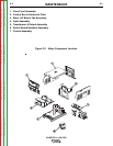
SWITCH BOARDS AND MAIN
TRANSFORMER
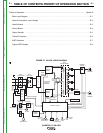
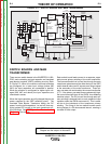
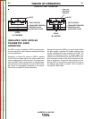
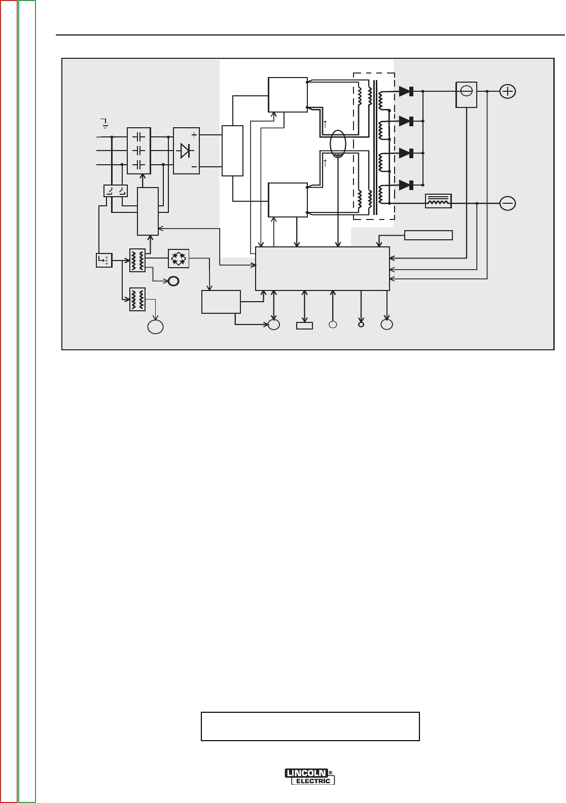
There are two switch boards in the INVERTEC® V450-
PRO, each containing an input capacitor and insulated
gate bipolar transistor (IGBT) switching circuitry. Refer
to Figure E.3. When the machine reconnect switches
are configured for a lower input voltage (below 300
VAC) the input capacitors are connected in parallel.
When the machine is configured for higher input volt-
ages (300 VAC and above) the input capacitors are
connected in series.
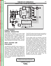
When the input capacitors are fully charged they act as
power supplies for the IGBT switching circuit. The
Insulated Gate Bipolar Transistors switch the DC
power, from the input capacitors, “on and off” thus sup-
plying pulsed DC current to the main transformer pri-
mary windings. See IGBT Operation Discussion and
Diagrams in this section.
E-3 E-3
INVERTEC® V450-PRO
FIGURE E.3 — SWITCH BOARDS AND MAIN TRANSFORMER
INPUT
C
ONTACTOR
INPUT
R
ECTIFIER
R
E
C
O
N
N
E
C
T
CONTROL BOARD
RIGHT
S
WITCH
BOARD
L
EFT
SWITCH
BOARD
M
AIN
TRANSFORMER
CURRENT
SENSOR
C
HOKE
OUTPUT
TERMINAL
OUTPUT
T
ERMINAL
POWER
B
OARD
1
15VAC
RECEPTACLE
P
O
W
E
R
S
W
I
T
C
H
I
N
P
U
T
B
O
A
R
D
FAN
M
OTOR
A
UX.
TRANS.
A
UX.
TRANS.
R
ECTIFIER
AUX.
RECONNECT
PRIMARY
CURRENT
SENSOR
WIRE FEEDER
RECEPTACLE
RS232
CONN.
T
HERMOSTATS
STATUS
LIGHT
T
HERMAL
LIGHT
CURRENT FEEDBACK
VOLTAGE FEEDBACK
65VDC
4
0VDC
C
ONTROL SIGNALS
P
WM
DRIVE
C
APACITOR
VOLTAGE
FEEDBACK
CAPACITOR
VOLTAGE
F
EEDBACK
P
WM
DRIVE
VOLTAGE
SENSE
R
ECEPTACLE
#1
#2
S
W
I
T
C
H
INPUT
C
ONTACTOR
INPUT
R
ECTIFIER
R
E
C
O
N
N
E
C
T
CONTROL BOARD
RIGHT
S
WITCH
BOARD
L
EFT
SWITCH
BOARD
M
AIN
TRANSFORMER
CURRENT
SENSOR
C
HOKE
OUTPUT
TERMINAL
OUTPUT
T
ERMINAL
POWER
B
OARD
1
15VAC
RECEPTACLE
P
O
W
E
R
S
W
I
T
C
H
I
N
P
U
T
B
O
A
R
D
FAN
M
OTOR
A
UX.
TRANS.
A
UX.
TRANS.
R
ECTIFIER
AUX.
RECONNECT
PRIMARY
CURRENT
SENSOR
WIRE FEEDER
RECEPTACLE
RS232
CONN.
T
HERMOSTATS
STATUS
LIGHT
T
HERMAL
LIGHT
CURRENT FEEDBACK
VOLTAGE FEEDBACK
65VDC
4
0VDC
C
ONTROL SIGNALS
P
WM
DRIVE
C
APACITOR
VOLTAGE
FEEDBACK
CAPACITOR
VOLTAGE
F
EEDBACK
P
WM
DRIVE
VOLTAGE
SENSE
R
ECEPTACLE
#1
#2
S
W
I
T
C
H
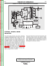
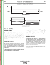
Each switch board feeds current to a separate, oppo-
sitely wound primary winding of the main transformer.
The reverse directions of current flow through the main
transformer primaries and the offset timing of the IGBT
switch boards induce an AC square wave output signal
at the secondary of the main transformer. These pri-
mary currents are monitored by the current transformer
(CT). If the primary currents become abnormally high,
the control board will shut off the IGBTs, thus disabling
machine output. The DC current flow through each pri-
mary winding is clamped back to each respective input
capacitor when the IGBTs are turned off. This is need-
ed due to the inductance of the transformer primary
winding. The firing of the two switch boards occurs
during halves of a 50 microsecond interval, creating a
constant 20 kHz output.
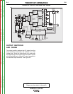
NOTE: Unshaded areas of Block Logic
Diagram are the subject of discussion
Return to Section TOC Return to Section TOC Return to Section TOC Return to Section TOC
Return to Master TOC Return to Master TOC Return to Master TOC Return to Master TOC