


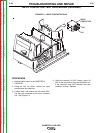
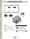
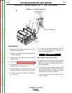


TRANSFORMER #2
3/8” MOUNTING
SCREWS (2)
P51
P52
P50
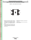
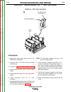
TRANSFORMER #2
3/8” MOUNTING
SCREWS (2)
P51
P52
P50
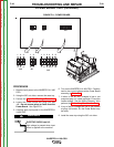
FIGURE F.7 – PLUGS P52 AND P54
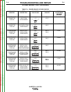
AUXILIARY TRANSFORMER NO. 2 TEST (continued)
TROUBLESHOOTING AND REPAIR
F-34 F-34
INVERTEC® V450-PRO
PROCEDURE
1. Remove the main input supply power to the
INVERTEC® V-450 PRO.
2. Remove any load that may be connected to the
115 VAC receptacle.
3. Using the 3/8 in. nut driver, remove the left and
right case sides.
4. Perform the Capacitor Discharge Procedure.
5. Locate plugs P50 and P51 at the Auxiliary
Transformer No. 2. See Figure F.7.
6. Carefully apply the correct input power and
check for 115 VAC at plug P51 pins #1 and #4.
7. If 115 VAC is present, the Auxiliary Transformer
No. 2 is good.
8. If 115 VAC is not present between pins #1 and
#4, check the associated leads and plugs for
loose or faulty connections.
High voltage is present at plug P50.
9. Carefully test for the correct AC input voltage
applied to the primary windings at H6 and H1.
(P50 Pins 1 and 5) Normal is 550-575 VAC.
See wiring diagram.
10. If the correct AC input voltage is applied to the
primary of the Auxiliary Transformer No. 2 and
the secondary voltage is NOT correct, the
transformer may be faulty. Replace.
11. Install the left and right case sides using the
3/8 in. nut driver.
WARNING
Return to Section TOC Return to Section TOC Return to Section TOC Return to Section TOC
Return to Master TOC Return to Master TOC Return to Master TOC Return to Master TOC