


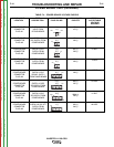
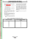

CURRENT TRANSDUCER TEST (continued)
TROUBLESHOOTING AND REPAIR
F-44 F-44
INVERTEC® V450-PRO
J8
216
211
212
213
P91
CURRENT
TRANSDUCER
1234
CONTROL BOARD
J8
5 6 7 8
1 2 3 4
J8
216
211
212
213
P91
CURRENT
TRANSDUCER
1234
CONTROL BOARD
J8
5 6 7 8
1 2 3 4
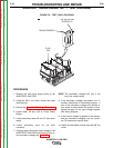
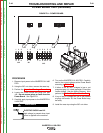
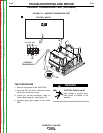
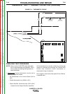
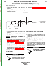
FIGURE F.10 – CURRENT TRANSDUCER TEST
TEST PROCEDURE
1. Remove input power to the V-450 PRO.
2. Using the 3/8” nut driver, remove the case
top and the control box cover.
3. Locate the current transducer leads at
Control Board plug J8. See Figure F.10.
4. Carefully apply input power to the V-450
PRO.
ELECTRIC SHOCK can kill.
High voltage is present when
input power is applied to the
machine.
WARNING
Return to Section TOC Return to Section TOC Return to Section TOC Return to Section TOC
Return to Master TOC Return to Master TOC Return to Master TOC Return to Master TOC