


ELECTRICAL DIAGRAMS
G-5
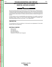
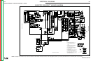
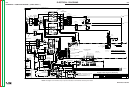
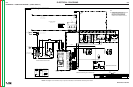
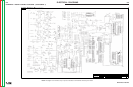
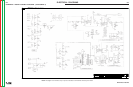
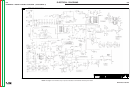
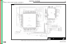
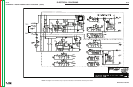
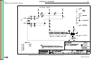
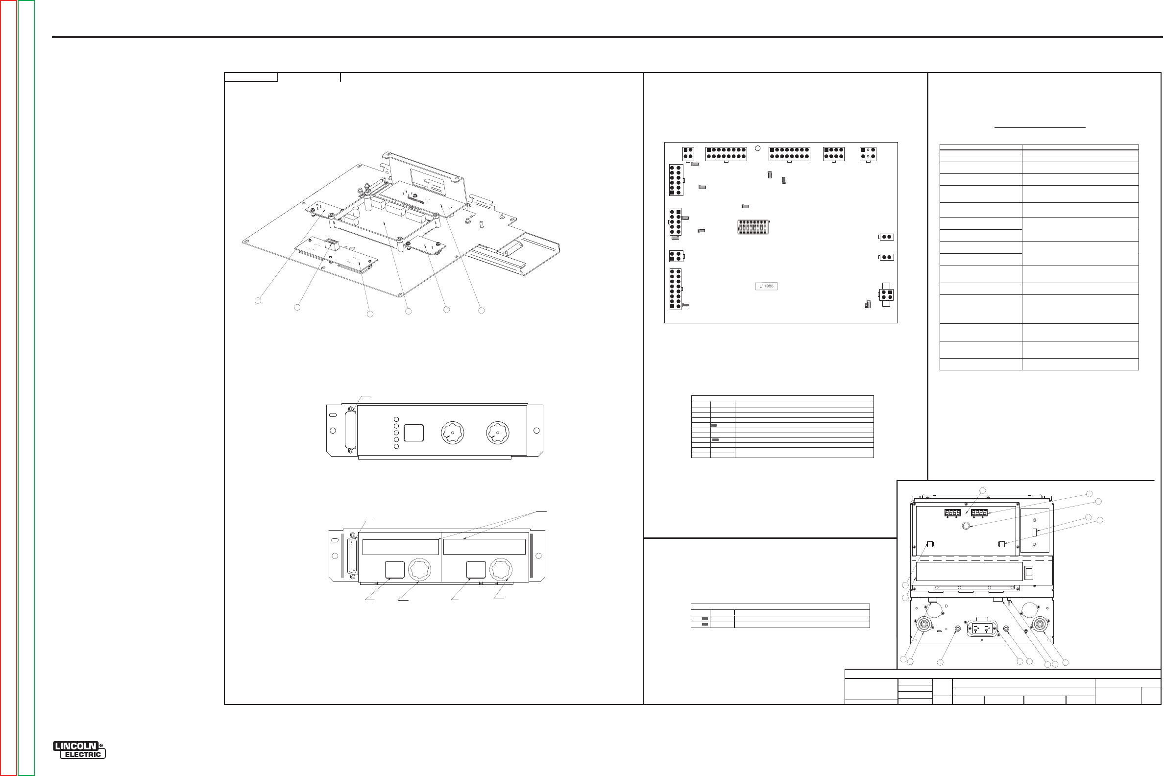
INVERTEC® V450-PRO
SCHEMATIC - COMPLETE MACHINE - (G4875 SHEET 3)
G4875
INVE
RTE
C V450-P
RO
MAC
HI
N
E SC
HEM
ATIC
NONE
G4421
DO NO
T
SC
AL
E
T
HIS DR
A
WING
EQ
UIP
M
ENT
TYPE:
SUBJECT:
SCA
L
E:
UF
CRM36847
3
PAGE ___ OF
___
3
E
NGI
N
EE
RI
NG
CO
NT
RO
LLE
D
MA
NU
FA
CT
URE
R:
No
THIS DOCUMENT CONTAINS PROPRIETAR
Y
INFORMATION OWNED B
Y
LINCOLN GLOBA
L, INC.
AND MA
Y
NOT BE DUPLICATED, COMMUNICATED
TO O
THER PARTIES OR US
ED FOR
AN
Y
PURPOS
E WITHOU
T
THE EXPRES
S WRIT
TEN PERMISSION
OF LINCOLN GLOBAL, INC.
PR
OP
R
IETA
R
Y &
CON
FI
DE
NTIAL:
t
MAT
ERI
A
L TO
L
ER
ANC
E ("
"
) TO A
GR
EE
WITH
PU
B
LI
SH
ED
ST
ANDARD
S.
ON A
LL
AN
GL
E
S I
S ± .5 OF
A D
E
GR
EE
ON
3
PLACE
D
E
CIM
ALS
IS
± .
00
2 i
n.
(
±
0.
0
5
mm)
ON 2
PL
AC
E D
ECIM
AL
S I
S ± .02 in. (
±
0.5 mm)
UNLESS OTHERWISE SPECIFIED TOLERANCE:
M
ANUF
ACTURING TO
L
ER
ANC
E
P
ER
E
2056
C
B2 AN
D F
U
SE, REVISED AMPS
R
EVISED
NOTE
N.B.
CHAN
GE
D
ET
AIL:
REFER
ENCE:
MA
T
ERI
AL
DIS
PO
SI
T
ION:
AP
PRO
VA
L
DA
T
E:
PROJ
EC
T
NUMBER:
DOCUMEN
T
NUMBER:
DOCUMEN
T
REV
ISI
ON:
IF PR
IN
T
ED
@ A
1
SIZ
E
UNI
T
S:
IN
CH
7-
13
-2
00
7
Dsn
ell
J.O'C
onn
or
.
DRAWN BY:
ENGINEER:
CL
EV
EL
AND
APPROVED:
CONTROL:
C
G4875
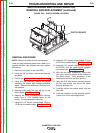
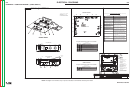
1.
Power Switch
2.
24V
-
42V
10 Amp Wire Feeder
Circuit Breaker
3.
115V
Auxiliary Power
&
Wire Feeder
Circuit Breaker
4.
6 pin Remote
5.
Work Stud
6.
Electrode Stud
7.
14 Pin
Wire feeder Remote
8.
Auxiliary Output (110V or 220V)
9.
STD Display Board
10.
Weld Terminal
/Remote ON
11.
Output
Control
/Remote Local
12.
Wire Feeder Polarity Switch
13.
Control Knob
14.
Mode Panel or (optional) Advance
Process Panel
f
ound underneath
Front Panel D
oor.
15. Thermal Light
Error codes for the
Invertec V450
-
PRO
The following is a list of possible error codes that the Power Wave can output via the status light
Error Code #
Indication
21 Unprogrammed Weld Mode.
Contact the Service Department for instructions on
reloading the Welding Software.
22 Empty Weld Table.
Contact the Service Department for instructions on
reloading the Welding Software.
23 Weld Table checksum error.
Contact the Service Department for instructions on
reloading the Welding Softwa
re.
31 Primary overcurrent error.
Excessive Primary current present. May be related to a
switch board or output rectifier failure.
32 Capacitor “A” under voltage
(Left side facing machine)
33
Capacitor “B” under voltage
(Right side facing machine)
Low voltage on the main capacitors. May be caused by
imp
roper input configuration, or an open/short circuit
in the primary side of the machine.
34
Capacitor “A” over voltage
(Left side facing machine)
35
Capacitor “B” over voltage
(Right side facing machine)
Excess voltage on the main capacitors. May be caused
by
improper input configuration, or an open/short
circuit in the primary side of the machine.
36 Thermal error
Indicates over temperature. Usuallyaccompanied by
Thermal LED. Check fan operation.
Be sure process
does not exceed duty cycle limit of the machine.
37 Softstart error
Capacitor precharge failed. Usually accompanied by
codes 32
-
35.
41 Secondary overcurrent error
The secondary (weld) current limit has been exceeded.
When this occ
urs the machine output will phase back
to 100 amps, typically resulting in acondition refered
to as “noodle welding”
43 Capacitor delta error
The maximum voltage difference between the main
capacitors has been exceeded. May be accompanied by
errors
32
-
35.
49 Single phase error
Indicates machine is running on single phase input
power. Usually caused by the loss of the middle leg
(L2).
Other
Use Snap Shot to interpret other errors
or Diagnostic
Sofware
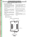
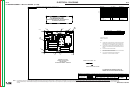
CONTROL BOARD
Description of LED
functions on the Invertec V450
-
PRO
For reference only
G3632 Digital Power Supply Board
LED #
COLOR
FUNCTION
1
Red
Indicates +5VDC SPI supply is present
2
Red
Indicates +5VDC co
ntrol supply is present
2
1
Inve
rt
ec V450
-
PR
O
LE
D
9
LE
D
10
LE
D
5
LE
D
1
LE
D
2
LE
D
3
LE
D
4
LED6
LED7
LE
D
8
S1
J11
J10A
J10B
POWER BOARD S
J5
J6
J7
J8
J9
J4
J3
J2
J1
1
1.
STD DISPLAY PC BOARD ASSEMBLY
2.
SPI ASSEMBLY
3.
REMOTE
PC
BOARD ASSEMBLY
4.
LED SELECT PC BOARD ASSEMBLY
5.
FACTORY MODE PANEL ASSEMBLY
5
2
3
3
4
6
5
7
Case front Detail
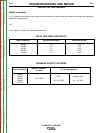
Description of LED fu
nctions on the Invertec V450
-
PRO
For reference only
L11088 Digital Control PC Board
LED #
COLOR
FUNCTION
1
Green
Indicates +15VDC from power supply board is present
2
Green
Indicates
–
15VDC from power supply board is present
3
Gre
en
Indicates +5VDC for +5SPI from power supply board is present
4
Green
Indicates +15VDC for +15SPI from power supply board is present
5
Green
Indicates +5VDC for +5V from power supply board is present
6
Green
Indicates +5VDC for +5VRS232 from power sup
ply board is present
7
Red
FAULT Signal (See software group for coding)
8
Green
Indicates +5VDC for +5CAN from power supply board is present
9
Green
10
Red
ArcLink Status Indicators (Main System
Master
ArcLink Connection) Solid
Green only when functional (Se
e software for error codes)
Fac
tory
Mod
e Panel
9
10
11
12
13
8
4
4
Control Panel
C-
C S
tick Sof
t
C-
C S
tick
cr
isp
Ti
g G
ta
w
C
V
W
ir
e
C
V
In
ners
hield
Hot
St ar t
ArcControl
Touc
h
Start
TI
G
Hi
-Freq
TI
G
So
ft
C
risp
WEL
D
MODE
Sele
ct
-1
0
+10
0
1
10
5
M
em
or
y
Sele
ct
Adj
us
t
Sele
ct
Ad
vance
Pr
ocess Panel
(O
pt
iona
l)
14
(S
1isn
ot
use
d)
8 Memo
ry
Select
weld process
(enco
der)
Select
Hot
Start
or Arc
Weld
Adjust
Hot
Start
&
Arc control
(encod
er)
A
lpha Numeric
Display
R
S232
R
S232
15
G-5
NOTE: This diagram is for reference only. It may not be accurate for all machines covered by this manual.
Return to Section TOC Return to Section TOC Return to Section TOC Return to Section TOC
Return to Master TOC Return to Master TOC Return to Master TOC Return to Master TOC