


Introduction
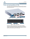
Power and Cooling Module (PCM)
1-4 SN0051103-00 A
S
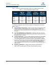
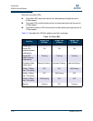
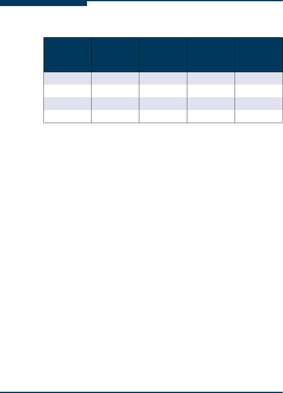
Table 1-1 shows the internal temperature limits set to trigger events or alerts.
The following paragraphs describe the fan speed and temperature parameters
listed in Table 1-1.
High Fan Speed Temperature – When a sensor detects a temperature that
exceeds this value, the fan speed will run at their maximum RPM. The
system logs the event and the system fault LED blinks five times every two
seconds.
Low Fan Speed Recovery Temperature – When the fans are running at
their maximum RPM and all sensors report values less than this value, the
fan speed resets to normal.
Critical Temperature – When a sensor detects a temperature that exceeds
this value, the system powers down the blade. When this happens, the
CPUs enter sleep state 5; the system sets the PCI power state of capable
devices to D3 and turns off the power supplies not essential to wake up the
CPUs. When the temperature goes below the Recovery Temperature
value, the sensor that reported the over temperature value will generate an
SMB_ALERT.
Recovery Temperature – Value at which a sensor will generate an
SMB_ALERT to wake up the CPU and cause the blade to reboot.
Table 1-1. Internal Temperature Sensor Limits
Sensor
High Fan
Speed
Temperature
Low Fan
Speed
Recovery
Temperature
Critical
Temperature
(power off)
SMB_Alert
Recovery
Temperature
Front
60°C 55°C 70°C 55°C
Rear
45°C 40°C 55°C 45°C
CPU1
60°C 55°C 68°C 55°C
CPU2
60°C 55°C 68°C 55°C