


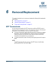
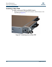


Removal/Replacement
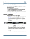
Power and Cooling Modules
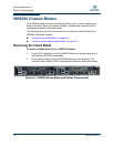
SN0051103-00 A 6-9
A
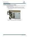
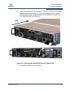
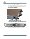
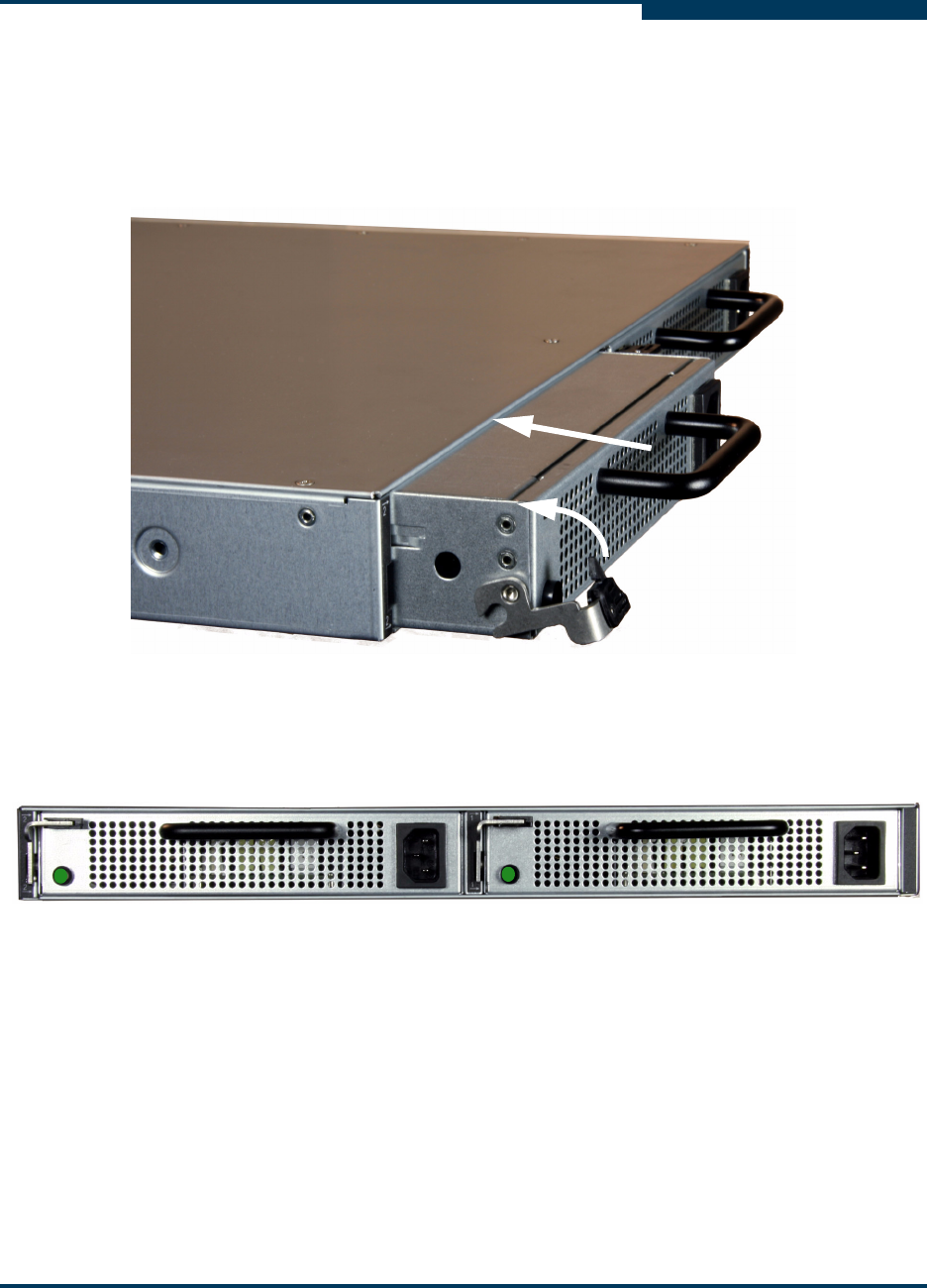
2. Insert the replacement PCM into the iSR6250 chassis. As shown in
Figure 6-6, push the PCM straight into the chassis (1) and make sure the
PCM is properly seated into the chassis mid-plane by pushing the lever up
and locking the latch in the up position (2). The PCM fans will turn on and
the LED should show an amber status.
Figure 6-8 Inserting the Replacement PCM
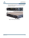
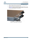
3. Connect the power cable to the newly inserted PCM. Its status LED should
change from amber to green within 5 seconds.
Figure 6-9 Back Side of Two PCMs - Both with Good Status Indicators
4. Verify that the airflow through both PCMs is in the same direction.
(1)
(2)