


Removal/Replacement
Power and Cooling Modules
6-6 SN0051103-00 A
S
Power and Cooling Modules
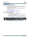
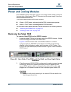
Each iSR6250 chassis blade has a power and cooling module (PCM), located on
the back side of the chassis. Each PCM consists of one power supply, three fans,
and one external status LED.
The PCM’s external status LED shows its status:
Green = GOOD status, indicating that the PCM is running as expected.
Amber = FAULT status, indicating that the PCM has failed.
You can remove and replace a failed PCM as described in the following sections:
“Removing the Failed PCM” on page 6-6
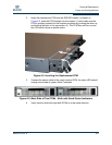
“Installing a New PCM” on page 6-8
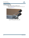
Removing the Failed PCM
To remove a failed PCM from the iSR6250 chassis:
1. Locate the failed PCM unit on the back side of the iSR6250 chassis. A failed
PCM unit displays an amber color status LED.
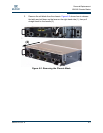
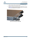
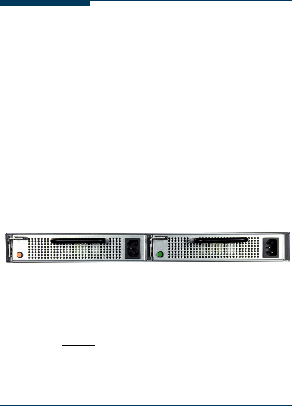
Figure 6-5 shows the back side of two PCMs installed in a chassis
configured with two iSR6250 chassis blades. The PCM on the left side
displays its fault indicator in amber, which indicates a FAULT status. The
PCM on the right side displays its fault indicator in green, which indicates a
GOOD status.
Figure 6-5 Back Side of Two PCMs with Fault (left) and Good (right) Status
Indicators
2. Check the second (GOOD) PCM to make sure it is ready to support storage
connectivity while you’re replacing the failed PCM unit. Make sure the
second PCM’s power cable is connected to the cable with the other end
plugged into a live power source and that it displays a green status LED.
CAUTION!
Failure to verify the functionality of the second PCM can result in lost
host storage connectivity.