


Prosine 2.5/3.0 Installation & Operation Guide 5
Section 2: Controls and Indicators
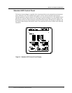
Prosine 2.5 inverter/chargers feature DC input and output connectors, an AC terminal block, a DIP
switch panel for custom configuration, three accessory jacks, an LED control panel for the PS2.5 and
an ACS panel for PS3.0, an LCD control panel, a cover for the AC connector block. The LCD control
panel is optional on the PS2.5 and standard on the PS3.0. DC terminal covers come standard with both
units. A replacement AC cover with a GFCI outlet is available as an accessory option for both the
PS2.5 and PS3.0.
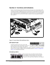
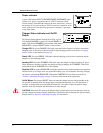
Figure 2. Prosine Chassis Side and Bottom Views
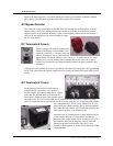
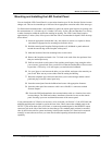
DIP Switch Panel
The DIP switch panel consists of two small, eight-
position up-down switches located under a cover on the
side of the Prosine inverter/charger: SW1 and SW2.
These switches are used to configure the Battery Type, Battery Temperature, Load Sensing, Audible
Signal, AC Service Rating, and Battery Size user-selectable options. See “Section 3: Configuration”
on page 25 for configuration instructions.
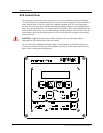
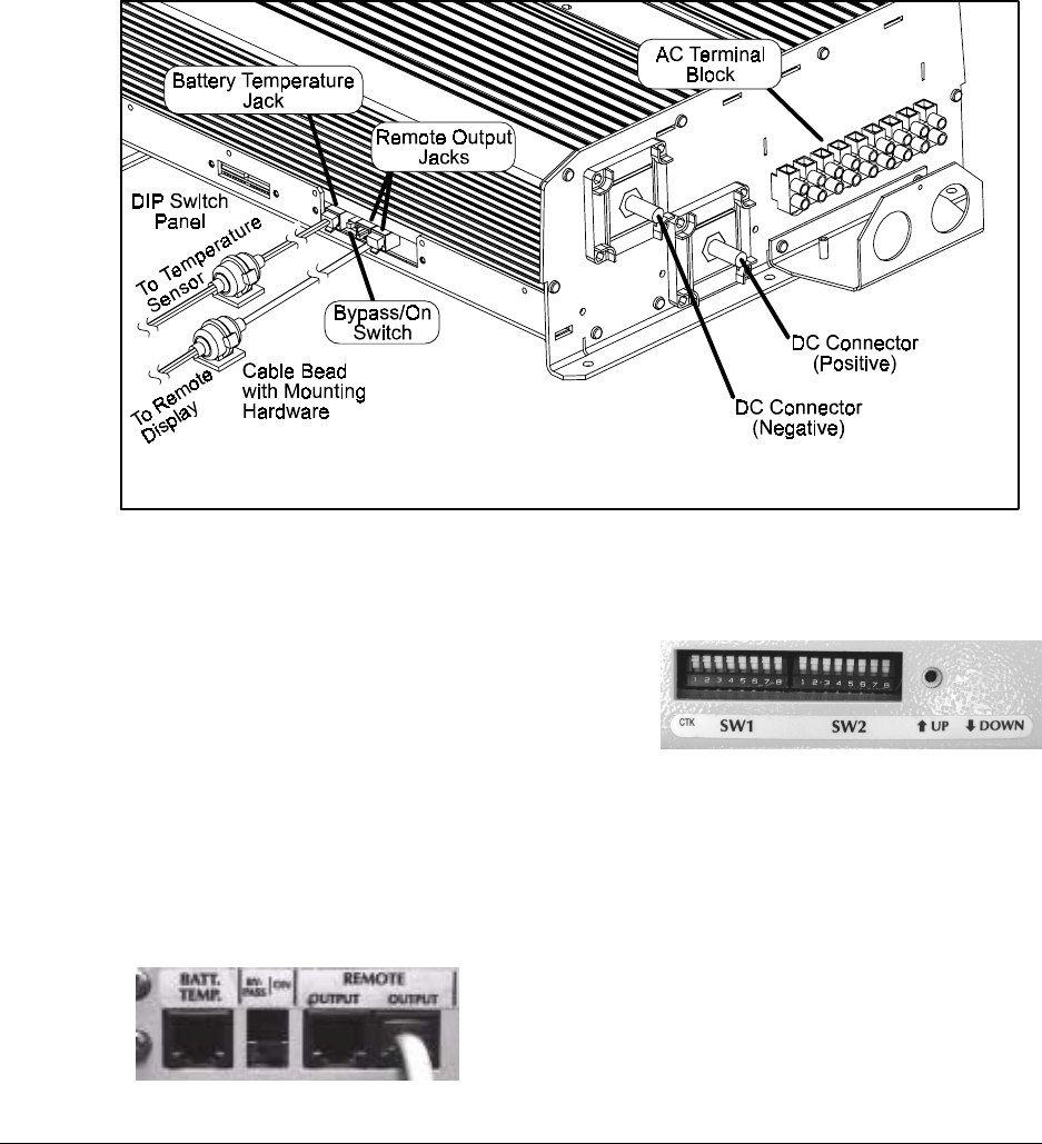
Accessory Jacks
Three accessory jacks are provided on the side of Prosine
inverter/charger: a battery temperature sensor jack (labeled
BATT TEMP) and two Remote Output jacks. The battery
temperature sensor reports battery temperature to the charger to