


DC Cabling
46 Prosine Installation & Operation Guide
DC Cabling
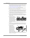
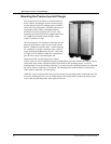
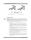
DC wiring includes the positive and negative conductors from the battery(s) as well as a disconnect
device and over-current protection. Locate your battery(s) as close as possible to your inverter (or
vice-versa) to reduce energy losses caused by cable resistance. Cables should be as short as possible
(5-10 feet) and large enough to handle the required current, in accordance with the electrical codes or
regulations applicable to your installation. The connectors on the inverter/charger are designed to fit
up to 500 MCM crimp-on ring terminals (either AMP or ILSCO) or box connectors.
Do not route your DC wiring through an electrical distribution panel, battery isolator, or other device
that will add additional voltage drops.
DC Over-Current Protection
Installation codes require over-current protection for battery cables, installed as close as possible to
the battery, in the positive side of the circuit. The current rating of this DC fuse or circuit breaker must
be large enough to allow the Prosine inverter/charger to operate your loads, but if the rating is too
high, electrical codes will require you to use larger DC cables than you would otherwise have to. The
fuse or circuit breaker must be rated for use on DC circuits. Fuses or circuit breakers rated only for AC
service are not suitable for use on DC circuits and may pose a hazard. The wire size used between the
inverter/charger and the fuse or circuit breaker must be sized to match the fuse or circuit breaker's
current rating, in accordance with the electrical codes or regulations applicable to your installation.
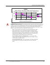
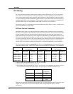
The following table outlines the minimum DC cable size and maximum fuse size required for some
common installation codes. There may be other codes and regulations applicable to your installation.
a
. Based on ABYC Recommended Practice E-9, 75C wire, no conduit.
b. Based on the NEC, NFPA 70, Article 551, 90C wire.
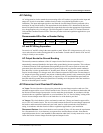
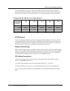
c. Based on NFPA 70, Article 240 and 310, 75C wire, wire in conduit. If your installation code allows you to wire
in free air, then the following table applies. NOTE: This table applies to residential installations only.
What the above tables do not take into account, however, is voltage drop associated with greater cable
lengths. It is always best to use oversize cables to reduce voltage drop and improve inverter
performance.
Marine Installation
See footnote a.
RV Installation
See footnote b.
Residential Installation
See footnote c.
Model
Wire Size Fuse Size Wire Size Fuse Size Wire Size Fuse Size
Prosine 2.5/12
# 2/0 AWG 350A # 3/0 AWG 350A 350 MCM 350A
Prosine 2.5/24
# 4AWG 175A # 3 AWG 175A # 2/0 AWG 175A
Prosine 3.0/12
# 3/0AWG 450A # 4/0 AWG 450A 500 MCM 400A
Prosine 3.0/24
# 2AWG 250A # 2 AWG 200A # 3/0 AWG 200A
Model Wire Size Fuse Size
(Amps DC)
Prosine 2.5/12 # 3/0 AWG
350A
Prosine 2.5/24 # 2 AWG
175A
Prosine 3.0/12 250
MCM
450A
Prosine 3.0/24 # 1 AWG
200A