


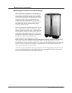
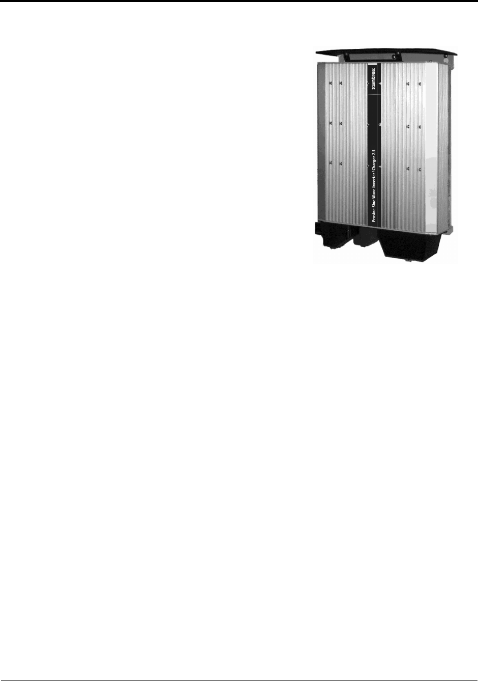
Mounting the Prosine Inverter/Charger
44 Prosine Installation & Operation Guide
Mounting the Prosine Inverter/Charger
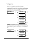
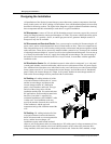
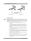
The inverter must be mounted on a vertical surface as
shown. Before mounting the Prosine inverter/charger,
test the chosen location for adequate space around the
unit to allow for connections, ventilation and access to
configuration DIP switches. Mounting hardware
should be corrosion resistant and #12 or #14. Your
mounting system should be able to support three times
the weight of the Prosine inverter/charger, which
weighs 32 pounds (14.5kg).
The more clearance for ventilation around the unit, the
better the performance. Allow at least 5 inches at the
bottom, 3 inches on each side, and 1.5 inches at the top
for ventilation. For better ventilation, route a fresh-air
supply through the bulkhead near the fans. This fresh-
air supply must be baffled or otherwise constructed to
prevent rain or spray from entering the unit.
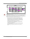
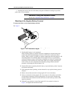
Mount the Prosine inverter/charger on a vertical
surface (such as a wall or bulkhead) using the mounting holes provided, with the DC and AC wiring
connections at the bottom. Mark the location of the holes on the mounting surface. Use all six
mounting holes. If you are installing a Prosine 3.0, you must use the mounting brackets provided with
the unit to allow for sufficient air circulation. The mounting holes on these brackets are spaced 16
inches apart to align with wall-stud spacing.
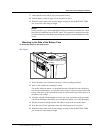
Attach the vent cover/drip shield to the top of the Prosine inverter/charger after securing the unit. The
screws for attaching this cover can be found already in the bracket holes. Remove the screws, place
cover in the slots and align holes, then replace the screws.