


Prosine 2.5/3.0 Installation & Operation Guide 25
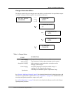
Section 3: Configuration
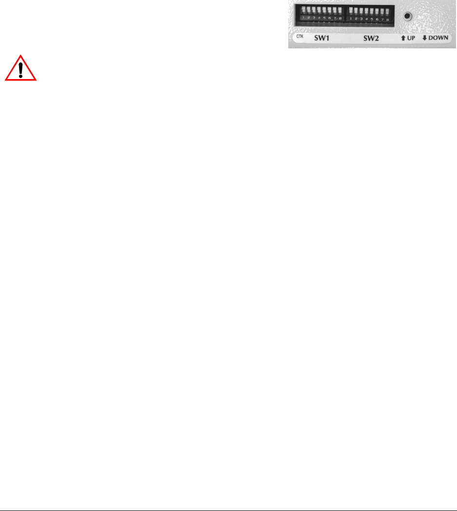
This section explains how to configure the Prosine inverter/charger to best meet your electrical system
requirements and get maximum performance using the DIP switches located on the side of the unit.
You will need a pen or other fine-pointed instrument to adjust the switches. Each switch has two
positions: Up and Down.
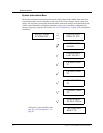
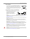
DIP Switch Settings
Each configuration parameter is defined in the list
below. DIP switch settings are described in the tables on
the next two pages. An asterisk (❃) indicates the factory
default settings.
WARNING Risk of battery damage and fire or explosion: “Installer settable” configuration items
are meant to be configured by a professional installer who is not only familiar with the system settings
of the inverter, but also the ramifications of changing those system settings. Setting these parameters
incorrectly can cause damage to your equipment or severely affect the performance of your system.
NOTE After configuring the inverter/charger using the DIP switches, make sure you replace the DIP
switch cover.
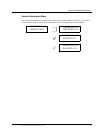
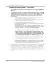
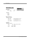
Battery Type
This is an “Installer-only” configuration item. Note the preceding Warning.
Settings are available for either flooded or gel electrolyte. Sealed batteries should
be charged as gel batteries even though they may have a liquid electrolyte. For fur-
ther details, see “Section 7: Batteries”.
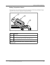
Battery
Temperature
With the battery temperature sensor installed, leave the switches in the WARM
position; they are ignored unless battery temperature falls below 5°C. Between
5ºC and -10ºC, the charger stops. If the temperature is below –10ºC, the tempera-
ture sensor is not detected, and the inverter/charger responds to the manual
defaults. With the battery temperature set to the average ambient temperature the
manual defaults are:
COLD: < 50ºF (10ºC),
WARM: between 50º F to 80º F (10ºC to 27ºC), and
HOT: > 80ºF (27ºC).
.
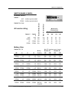
Load Sense
This setting determines what power level the inverter has to detect before it will
auto start. Setting this value to 0 will cause the inverter to remain on all the time.
Note that extremely low power loads (e.g. digital clocks on microwaves) may
require the 0 setting in order for the inverter to stay on.
Audible Alarm
This switch turns the audible alarm On or Off.
AC Service
Rating
The maximum AC current that the Prosine inverter/charger will draw from shore-
power is determined by this value. If you find that the Prosine inverter/charger
keeps tripping the utility power breaker, set this value to a lower level. This value
may limit the maximum charging current to your batteries, depending also upon
battery capacity.
Battery Size
This is an “Installer-only” configuration item. The capacity of the battery or bat-
tery bank in amp-hours. Note the preceding Warning: charging at a rate too high
for your batteries can damage and/or destroy them.