


Prosine Installation & Operation Guide 45
Section 4: Inverter/Charger Installation
AC Cabling
AC wiring must be sized to match the current rating of the AC breakers you provide on the input and
output AC circuits in accordance with the electrical codes or regulations applicable to your
installation. The input and output circuits to and from the inverter/charger must be protected with a
maximum 30-amp circuit breaker. The output branch circuit breaker size is determined by the load
that will be placed on the circuit. Determine the output load, then select the appropriate circuit breaker
size, the appropriate wire size and type. The following table is based on the U.S. National Electrical
Code and the Canadian Electrical Code. There may be other codes and regulations applicable to your
installation.
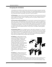
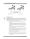
AC and DC Wiring Separation
Do not mix AC and DC wiring in the same conduit or panel. Where DC wiring must cross AC or vice-
versa, make the wires at the crossing point 90° to one another. Consult code for details of DC and AC
wiring in vicinity to one another.
AC Output Neutral-to-Ground Bonding
The neutral (common) conductor of the AC output circuit of the Prosine inverter/charger is
automatically connected (bonded) to the input safety ground during inverter operation. This conforms
to National Electrical Code requirements that separately derived AC sources (such as inverter and
generators) have their neutral conductors tied to ground in the same way that the neutral conductor
from the utility is tied to ground at the AC breaker panel. When AC utility power is present and the
Prosine inverter/charger is in charger mode, this connection (neutral of the Prosine inverter/charger’s
AC output to input safety ground) is not present so that the utility neutral is only connected to ground
in one place, at your AC input breaker panel, as required. Your AC load distribution panel must not
bond the neutral to ground. Many sub-panels have a bonding screw designed to allow the installer to
bond or un-bond the panel’s neutral.
AC Disconnect and Overload Protection
AC Input: The circuit breaker or fuse used to protect the inverter/charger must be rated max. 30A,
and must be approved for use on 120VAC branch circuits. The wire size used between the breaker and
the Prosine inverter/charger input must be sized to match the circuit breaker, in accordance with the
electrical codes or regulations applicable to your installation. The "AC Service Rating" setting of the
Prosine inverter/charger must also be set to match the size of the breaker provided.
AC Output: The circuit breaker or fuse used must be rated max. 30-amp, and must be approved for
use on 120V AC branch circuits. The wire size used between the Prosine inverter/charger output and
the breaker, and between the breaker and your loads, must be sized to match the circuit breaker’s
rating, in accordance with the electrical codes or regulations applicable to your installation.
Disconnect Devices: Since circuit breakers can be turned off, they will also meet the requirement
for a disconnect device. As an alternate, use separate fuses and disconnect switches. Note that the
required disconnect device is not intended for disconnection under load, it is only meant to be a way to
isolate the Prosine inverter/charger from the input and output circuits.
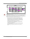
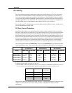
Recommended Wire Size vs Breaker Rating
Breaker Size
10A 15A 20A 30A
Min Wire Size
14AWG 14AWG 12AWG 10AWG