


Prosine 2.5/3.0 Installation & Operation Guide 7
Section 2: Controls and Indicators
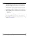
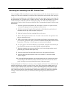
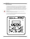
Standard LED Control Panel
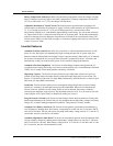
The Prosine inverter/charger is supplied with a control panel that can be mounted into an instrument
panel, bulkhead or wall. The standard control panel is used to report information about Prosine
operating parameters and the external AC and DC power sources connected to it. The standard control
panel has five separate functional divisions: the Battery Status LED display, the Faults Display and
Reset Button, the Inverter Status Indicator and On/Off Control Button, the Shorepower Indicator, and
the Charger Status Display and On/Off Control. These functional divisions are shown in the following
illustration.
Figure 3. Standard LED Control Panel Display