


Prosine Installation & Operation Guide 53
Section 4: Inverter/Charger Installation
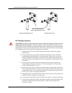
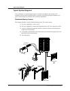
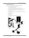
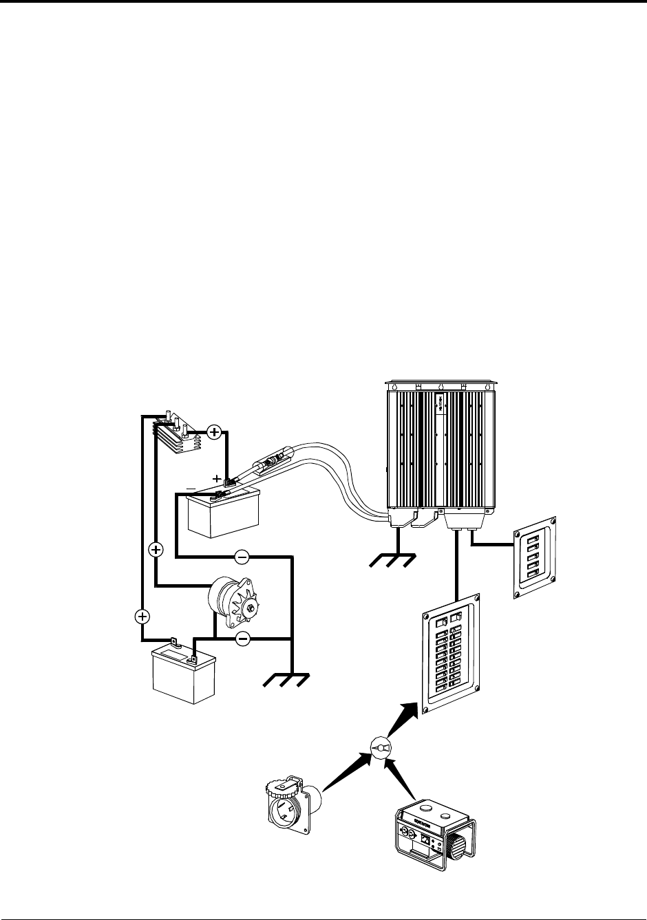
Recreational Vehicle System
The diagram below illustrates a typical RV system with the following components:
1. AC power supplied from a shorepower connector
2. AC power supplied from a generator
3. AC Source Selector switch that isolates the two AC supply sources
4. AC distribution panel that provides a 30-amp circuit breaker that feeds the inverter
5. AC sub-panel with branch circuit breakers that supply only inverter loads
6. Inverter/charger
7. DC power supplied by a house battery bank that is isolated from the vehicle starting
batteries
8. Vehicle starting battery
9. Battery isolator
10. DC alternator
11. Chassis grounds for both the inverter and the DC components
DC Fuse or
Circuit Breaker
AC Sub Panel
Main AC Panel
Automatic or Manual
Source Transfer Switch
Generator
Battery Isolator
12 Volt Deep
Cycle Battery
Vehicle Start
Battery
Chassis Ground
Chassis Ground
Shore Power
Prosi ne Si newave Inverter / Charger 2.5
➄
11
!
"
#
$
%
&
'
(
)
*
➄
11