


Prosine Installation & Operation Guide 47
Section 4: Inverter/Charger Installation
For best performance, the wire sizes shown in the table below will allow the Prosine to operate
properly. Please note that regulatory requirements may not allow you to use the wire size given for 5
foot and 10 foot distances. Also, increasing the wire size will provide longer inverter performance.
DC Disconnect
If a DC circuit breaker is used to provide over-current protection for the battery circuit, it will also
meet the requirement to provide a disconnect. If a DC fuse is used to provide over-current, however, a
separate DC disconnect switch or a combined “fusible disconnect” will be required. As with the AC
disconnects, the DC disconnect is not intended for disconnection under load.
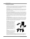
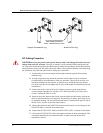
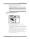
Battery Cable Routing
When a distance separates positive and negative battery cables, they have much more inductance than
if they are close together, and when the high current drawn by the inverter is flowing, strong magnetic
fields are generated. These fields may interfere with sensitive equipment, so it is very important to
route the positive and negative cables in parallel, as close together as possible.
DC Cabling Connections
Color-code your battery cables with colored tape or heat shrink tubing. The standard is red for
positive (+) and black for negative (–).
Use crimp-on ring terminals or set-screw type pressure connectors (i.e., “box lugs”).
For marine installations, you must use a wire protector between the set-screw and stranded wire.
If you are using crimp-on terminals, use the manufacturer’s recommended crimping tool to install
them.
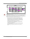
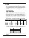
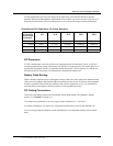
Recommended DC Cable Sizes For Proper Operation
Cable Length
in Feet (from
invert/charger
to battery)
5 ft 10 ft 15 ft 20 ft 30 ft
PS 2.5 12-volt
2/0 AWG 250MCM 350MCM 500MCM 750MCM
24-volt
2 AWG 2/0 AWG 4/0 AWG 250MCM 350MCM
PS 3.0 12-volt
3/0 AWG 350MCM 500MCM 750MCM 1000MCM
24-volt
1 AWG 3/0 AWG 250MCM 350MCM 500MCM