


Prosine 2.5/3.0 Installation & Operation Guide 9
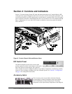
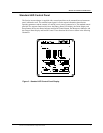
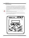
Section 2: Controls and Indicators
Fault LED This LED flashes on-and-off during an error condition from which the unit will
automatically recover and restart when the condition is remedied. The FAULT LED will be lighted
steadily when any error occurs from which the inverter/charger cannot automatically recover. It is
usually necessary to disconnect the AC or DC supply to recover from this type of error. An error
condition is accompanied by an audible alarm if the alarm is enabled.
Temp LED This LED flashes on-and-off to indicate that the internal temperature of the Prosine
inverter/charger is too high and the unit has shutdown. When the internal temperature of the unit cools
sufficiently, the inverter/charger will automatically restart. The audible alarm that accompanies this
condition (if enabled) will also be silenced upon auto-restart.
Reset Button The RESET button on the Faults panel has two functions: pressed and released, it
will silence the audible alarm which, if enabled, will sound an insistent intermittent tone anytime an
error condition occurs, which can be looked up in a table to determine the nature of the error. Press
and hold the RESET button to display error codes. Error codes are listed in an Appendix to this
manual.
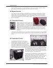
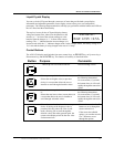
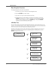
Inverter Status Indicators and On/Off Button
Invert LED When the green LED labeled INVERT is flashing,
shorepower is not present, Load Sense is enabled, and no AC
loads exceed the Load Sense threshold. The inverter is not
producing AC power from the batteries. When the INVERT
LED is lighted steadily, shorepower is not present and the
inverter is producing AC power from the batteries. The INVERT LED is not lighted when shorepower
is present.
Standby LED When the amber LED labeled STANDBY is lighted steadily, shorepower is present
and the inverter will pass AC power through to any AC loads that may be present.
If shorepower should fail or be removed while the inverter is in Standby mode, the inverter will
automatically begin to produce AC power from the batteries, and the INVERT LED will be lighted.
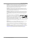
On/Off Button. A button labeled ON/OFF is provided adjacent to the INVERT and STANDBY
LEDs. When pressed, this button switches the inverter from On to Standby mode. Use in conjunction
with the charger’s ON/OFF button to set the startup inverter/charger mode. See “Section 3:
Configuration‚” on page 25 for instructions on how to set the startup inverter/charger mode.