


Designing the Installation
40 Prosine Installation & Operation Guide
Designing the Installation
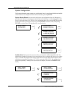
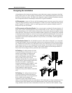
All installations of the Prosine inverter/charger system share many common components, described
briefly in this section. AC & DC cabling, circuit breakers, fuses, and distribution panels are more fully
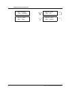
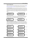
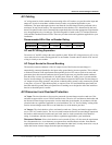
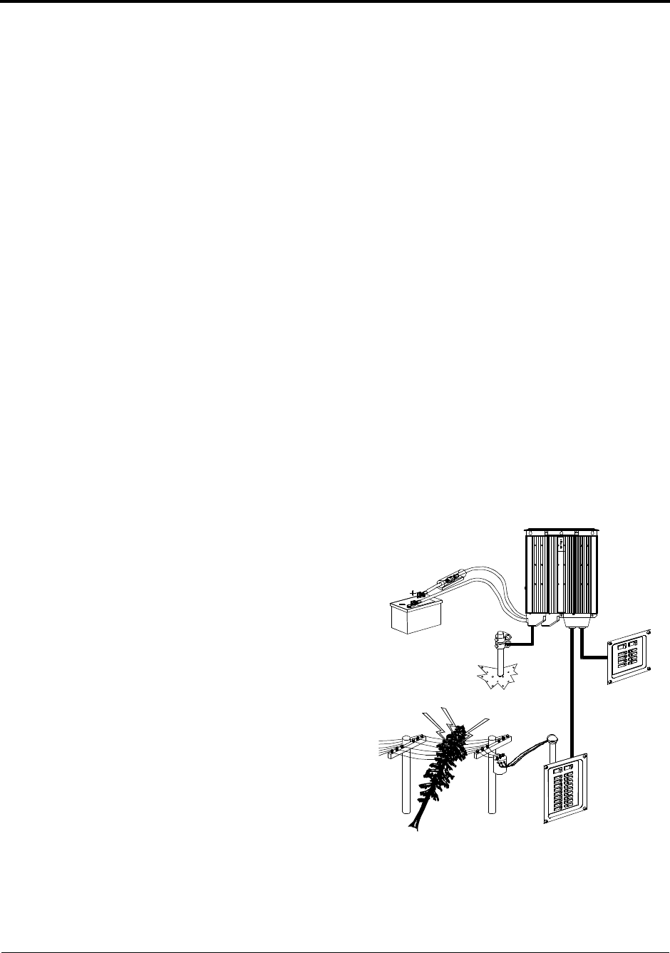
described in following sections. The figure below diagrams a typical residential installation showing
these components and their relationship to each other in a typical installation.
AC Shorepower A source of 120-volt, 60-Hz alternating current is necessary to provide a source of
energy for charging batteries, and to pass-through to AC loads. This source could be the utility grid or
power company, or a gasoline-, diesel-, or natural gas-powered AC generator. Multiple sources of
shorepower may also be available.
AC Disconnect and Overload Device Every system requires a method of disconnecting the AC
power source, and an overload protection device (circuit breaker or fuse). These two components are
often integrated into an AC circuit breaker, which provides a disconnect and protects against overload
at the same time. These devices are usually installed within a protective box. Some provide a method
of selecting between multiple AC sources as well as circuit protection and disconnect. You can use up
to a 30-amp circuit breaker in the AC supply line feeding the inverter/charger. The current rating of
the breaker or fuse must be matched to the wire size(s) involved, in accordance with the applicable
installation codes.
AC Distribution Center The AC distribution center is often called a ‘main panel,’ or a ‘sub panel.’
A main panel includes a main circuit breaker, which serves as a disconnect for the AC power supply
line. Additional circuit breakers serve individual circuits, one of which may serve the inverter/charger.
Some systems route all AC service through the inverter/charger, in which the main AC distribution
panel is fed by the inverter/charger AC output. In all systems, both the inverter/charger and the AC
loads on the inverter/charger must be protected with circuit breakers.
AC Cabling AC cabling includes all of the
wires and connectors between the AC source
and the inverter/charger; and between the
inverter/charger and the AC distribution
panels, circuit breakers, and loads. The type
and size of the wiring varies with the
installation and the load. For marine and some
RV applications, flexible multiple-strand wire
known as ‘boat cable’ is required. For
residential installations, solid ‘ROMEX’ cable
is often used. Your installation code may
specify the number of strands, the overall size
of the conductors, and the type and
temperature rating of the insulation around the
wire.
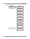
DC Cabling DC cabling includes all of the
wires and connectors between the batteries,
the DC disconnect and over-current protection
device, and the inverter/charger. All
installations require multi-strand insulated
cables as well as disconnect and over-current devices. DC cables come in a large assortment of sizes,
indicated by the AWG notation or the kcmil (MCM) notation. AWG refers to the American Wire
Gauge standard, while kcmil refers to thousands of circular mils. Under the AWG standard, a larger
AC Sub-panel
AC Main Panel
120Vac from
Utility Grid
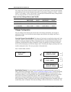
DC Fuse or
Circuit Breaker
Prosi ne Si newave I nverter / Charger 2.5