


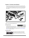
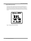
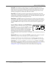
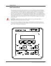
Standard LED Control Panel
8 Prosine 2.5/3.0 Installation & Operation Guide
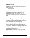
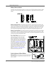
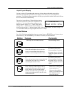
Battery Status Indicator
The Battery Status LED Display includes two vertical series of LEDs that indicate the battery voltage
and current. A conversion table enables you to estimate the AC output from the inverter by the DC
current.
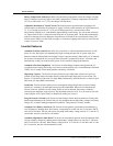
Battery Voltage Indicator This indicator reports the battery voltage at the input terminals of the
Prosine inverter/charger. At low currents, the indicator is very accurate. At high currents, the indicated
voltage will be somewhat lower than the actual battery voltage due to voltage drop across the cables
between battery and inverter. The range of the battery voltage indicator is from 10.0 to 16.75 volts
DC. The LEDs do not light until the voltage level exceeds the value printed alongside the LED.
Battery Current Indicator This indicator reports the current drawn by the Prosine inverter/charger
from the batteries. It does not indicate current drawn by other loads connected to the batteries. High
current loads (over 200A) are displayed by yellow LEDs. The LEDs do not light until the current level
exceeds the value printed alongside the LED.
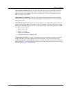
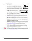
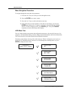
Error Code Display When an error occurs,
either the Warning, the Fault, or the Temp
LED will be lighted, as well as one of the
Battery Voltage LEDs, and one of the Battery
Current LEDs. These three LEDs indicate an
error code that you can look up on the Error.
Code table in “Appendix C: Troubleshooting”
to assist in determining the nature of the error
In the example at right, the Warning, 10V, and
100A LEDs are flashing, and the error code
indicated is derived from the value shown in
parenthesis, in this case: 206. Look in the
tables in “Appendix C: Troubleshooting” to
determine the meaning of the code.
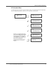
Faults Indicators & Reset Button
Warning LED This LED flashes on-and-off for the duration of
any error condition, accompanied by an audible alarm if the
alarm is enabled.