


Prosine Installation & Operation Guide 37
Section 4: Inverter/Charger Installation
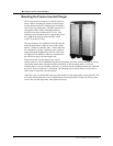
This section describes the tools and materials required, the appropriate location and environment for
mounting the inverter/charger, AC and DC cabling, and step-by-step instructions to install the unit. A
number of diagrams for various types of installations are provided. These instructions are intended to
be used as a guide only. It is the installer’s responsibility to observe all safety and appropriate
installation regulations and to proceed accordingly.
Read the entire chapter first before commencing the installation to ensure you have all the materials
necessary to install the PS2.5/3.0 and that is is being installed in an appropriate environment.
WARNING: FIRE, SHOCK, AND ENERGY HAZARD Installation should be performed by
certified and experienced technicians familiar with inverter/charger installations and the applicable
installation codes.
Governing installation codes will vary depending upon the specific location and application of the
inverter/charger installation. Installations may be governed by the Code of Federal Regulations
(CFRs), the American Boat and Yacht Council, (ABYC), National Electrical Code (NEC), Canadian
Standards Association (CSA), Canadian Electrical Code (CEC), RV Industry Association (RVIA) or
others. For complete and authoritative installation regulations contact the appropriate regulatory
agency.
Safety Instructions
Before beginning the installation of the Prosine inverter/charger, review the safety instructions at the
beginning of this manual, and read this entire section. Disconnect all sources of AC and DC power to
prevent accidental shock. Disable and secure all AC and DC disconnect devices and automatic
generator starting devices. Use the DIP switches to configure the inverter/charger after reading
”Section 3: Configuration” page 25. If you have the ACS Control panel, you can configure the unit
after installation, but before operating.
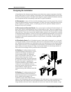
Installation Overview
Experienced and licensed installers familiar with inverter/charger installations may follow the steps
listed below to install the Prosine 2.5/3.0 inverter/charger. For system component recommendations
and requirements, refer to each specific section in this manual. For instance, the ”AC Cabling” section
describes AC wiring guidelines, while the ”DC Cabling” section describes DC wiring guidelines.
This is an overview only. If you are unsure of any aspect of inverter/charger installation, read the
entire manual, cover to cover, before attempting to perform an installation.
1. Before beginning any installation, disconnect all sources of power, both AC and DC.
2. Remove the Prosine inverter/charger from the shipping container and verify that all
components are present. Record the model and serial number on the packaging page of
this manual.
3. Slide the BYPASS/ON switch on the side of the Prosine inverter/charger to BYPASS.