


Typical System Diagrams
52 Prosine Installation & Operation Guide
Typical System Diagrams
Every installation is a custom-designed system. It could be a residential, solar, marine, or RV
installation with an almost unlimited number of variations. The following diagrams illustrate a few
typical system designs for residential, solar, and marine installations.
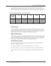
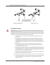
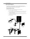
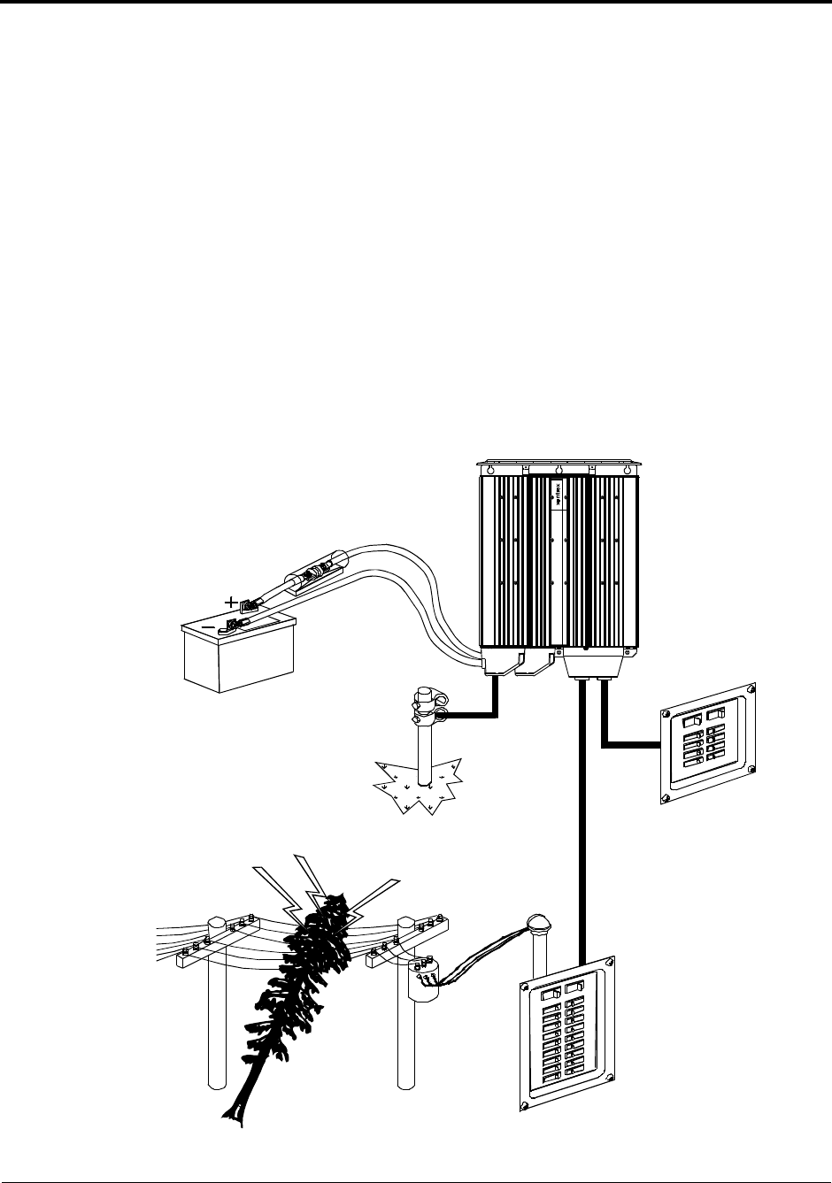
Residential Backup System
This diagram illustrates a typical residential backup system. This system features:
1. AC power supplied by a utility system
2. DC power supplied by a battery bank and protected by a DC fuse in the positive cable
3. A main AC distribution center that includes a maximum 30-amp circuit breaker that
supplies the inverter/charger
4. A sub-panel AC distribution center with branch circuit breakers that supply only loads
that run off of the inverter/charger
5. The earth ground
d
AC Sub-panel
AC Main Panel
120Vac from
Utility Grid
DC Fuse or
Circuit Breaker
Pr os i ne S i newave Inverter / Charger 2.5
!
"
#
$
%