


Mounting and Installing the ACS Control Panel
22 Prosine 2.5/3.0 Installation & Operation Guide
Mounting and Installing the ACS Control Panel
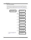
You can install the ACS Control Panel in a convenient location up to 50 feet from the Prosine inverter/
charger unit.
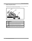
For flush mount installation onto a wall, bulkhead, or panel, the remote panel requires an opening with
the measurements of 4-1/8 inches by 4-1/8 inches (10.5cm by 10.5cm). Be sure that there is no wiring
or other obstruction within the wall before making an opening. The LCD Control Panel requires
approximately 2 inches (5cm) of free space within the wall to accommodate its depth. Follow the
steps shown below:
1. Select an appropriate location that is dry, not subject to corrosive or explosive fumes,
and otherwise appropriate for mounting an electronic device.
2. Hold the control panel faceplate flush against the wall, bulkhead or panel and mark
around the outside edge of the faceplate with a pencil.
3. Mark the location of the four mounting holes at each corner.
4. Remove the faceplate and mark a line 7/16-inch inside each of the four perimeter lines
that you marked previously.
5. Drill an access hole at each corner of the resulting small square large enough to allow
you to insert a jigsaw blade. Place your drill bit so that the finished hole will not extend
beyond the 4 1/8-inch by 4 1/8-inch square you marked on the bulkhead.
6. Use your jigsaw to cut between the holes you just drilled, and remove the material you
just cut out. Blow out any waste residue from the cutting and drilling.
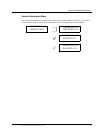
7. Route the telephone-type connector cable from your inverter/charger and the control
panel and plug it into the receptacle labeled “INPUT” on the back of the control panel.
You can add another ACS panel in series to the first ACS panel by plugging the second
ACS panel into the receptacle labeled “OUTPUT” on the back of the first ACS panel.
8. Insert the control panel into the bulkhead and secure with appropriate fasteners.
9. Insert the other end of the connector cable into the one of the RJ-11 connectors marked
“Remote Output” on the Prosine inverter/charger. You can connect another control
panel to the other output connector on the inverter/charger if you desire.
10. Secure the EMI bead attached to the communications cable to a location close to the
inverter/charger. The EMI bead reduces interference from the inverter on the control
panel. Securing it prevents accidental disconnect of the remote panel.
If you purchased the ACS Panel as an accessory to be used with your Prosine 2.5, the ACS Panel and
standard supplied panel can both be used at the same time. Either connect the standard panel to the
OUTPUT jack on the back of the ACS Panel, or connect the standard panel to the REMOTE output
connector jack on the side of the Prosine inverter/charger. The standard panel can then be mounted
close by the Prosine unit for system monitoring in that location and the ACS Panel can be mounted
remotely in some other area where you want more detailed operating information and control
capability.