


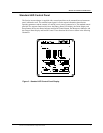
AC Bypass Selector
6 Prosine 2.5/3.0 Installation & Operation Guide
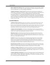
optimize the charging profile. The remote output jacks enable you to remotely mount the standard
and/or the ACS control panels, described later in this section of this manual.
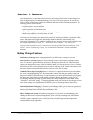
AC Bypass Selector
The small slide switch located between the Batt Temp jack and the Remote Output jacks is the AC
Bypass selector switch. The default position of this switch is On. In the On position, the inverter/
charger operates as programmed. When the switch is in the Bypass position, the inverter/charger is
Off, and AC current bypasses the inverter/charger to supply
the AC loads directly.
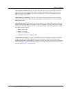
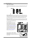
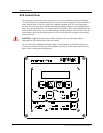
DC Terminals & Covers
The DC cabling connectors are located on the
bottom of the Prosine inverter/charger. Each
connector is an M10 x 1.5 stainless steel stud
and nut. The studs are about 1-inch long and
approximately 3/8-inch in diameter. Use a 17mm (~11/16-inch) wrench. Two color-
coded covers, a red one for the positive terminal and a black one for the negative
terminal, are provided for preventing accidental contact with these connectors after
installation.
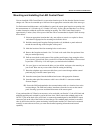
Adjacent to the DC terminals is the chassis ground lug. The chassis ground lug provides a ground path
for DC fault current from the inverter/charger chassis to ensure your battery fuse opens in the event of
a fault.
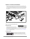
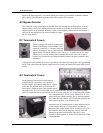
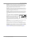
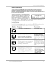
AC Terminals & Covers
On the bottom of the Prosine inverter/charger,
alongside the DC connectors, a nine-position
terminal block is provided for attaching AC cabling
to the unit. The terminal block is divided into AC-
Input and AC-Output sections. One terminal each is
provided for the AC Line-In (Hot) cable, the AC Neutral-In cable, and the AC Ground-In (GND)
cable. Two terminals each are provided for the AC Line-Out cable, the AC Neutral-Out cable, and the
AC Ground-Out cable. All are clearly labeled. The AC Line
cable usually has a black insulator, the AC Neutral generally
has a white insulator, and the AC Ground cable generally has
either a green insulator, or no insulator at all.
Adjacent to the AC terminal block is a black bracket with two
1-inch diameter holes in it. This bracket is provided for
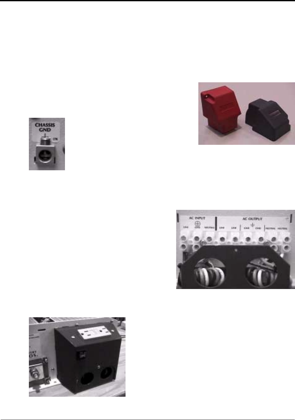
attaching cable clamps (strain reliefs) or conduit. A cover is
provided that slides into the end plate of the inverter and
attaches to the strain-relief bracket. This cover is also
available with an optional AC duplex GFCI outlet and 15-amp
circuit protector.