


1 – 4
VSG/VSSG • Installation, Operation and Maintenance Manual •Vilter/Emerson • 35391SSG
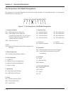
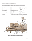
1 - Motor
2 - Coupling
3 - Suction Strainer
4 - Suction Check Valve
5a - Suction Stop Valve
5b - Suction Stop Butterfl y Valve
(Typically Shipped Loose)
6 - Compressor
7 - Discharge Pipe
8 - PLC Panel
9 - Block & Bleed Assembly
10 - Oil Pump
11 - Oil Heater
12 - Oil Separator
13 - Oil Temperature Control Valve
(Oil Mixing Valve)
14 - Oil Pump Strainer
15 - Oil Sight Glass
16 - Oil Filter
(Optional Dual Oil Filters Shown)
17 - Discharge Connection
18 - Oil Separator Inspection Port
19 - Thermal/Acoustic Oil Separator
Blanket
(Optional Per Application)
20 - Nameplate
21 - Heat Trace Insulation
(Optional Per Application)
22 - Frame
23 - Oil Cooler (Shell and Tube Heat
Exchanger)
23 4 5a
6
8
1013
16
1
17
9
7
1112141511
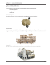
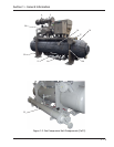
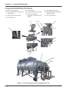
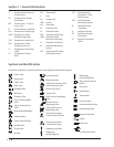
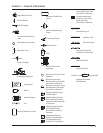
Compressor Unit Component Identifi cation
Each gas compressor unit may differ, but below are typical components that can be found on each unit.
Figure 1-2. Gas Compressor Unit Components (1 of 3)
Section 1 • General Information
5b