


TOC - 3
VSG/VSSG • Installation, Operation and Maintenance Manual •Vilter/Emerson • 35391SSG
Tables
Table 3-1. Long Term Storage Compressor Hardware .............................................................................3-2
Table 3-2. Maximum Allowable Flange Loads .........................................................................................3-11
Table 4-1. Command Shaft Rotation Specifi cations ................................................................................4-6
Table 5-1. Maintenance/Service Schedule ..............................................................................................5-1
Table 5-2. Oil Filter Elements and Compressor Models ............................................................................5-6
Table 5-3. Shaft and Hub Distances ........................................................................................................5-10
Table 5-4. Hub Clamp Bolt and Set Screw Torque Specifi cations .............................................................5-12
Table 5-5. Disc Pack Installation Torque Specifi cations ...........................................................................5-12
Table 5-6. Clamping Bolts and Set Screw Torque Specifi cations..............................................................5-14
Table 5-7. Maximum Bearing Float (Compressor Shaft) ..........................................................................5-17
Table 5-8. Gate Rotor Float .....................................................................................................................5-18
Table 5-9. Gate Rotor Tool Sets ...............................................................................................................5-21
Table 6-1. Slide Valve Actuator Troubleshooting Guide (1 of 2) ...............................................................6-1
Table 6-2. Slide Valve Actuator LED Blink Codes* (1 of 2) ........................................................................6-3
Table 6-3. Troubleshooting Guide - General Problems & Solutions (1 of 3) ..............................................6-5
Figures
Figure 1-1. Gas Compressor Unit Model Designation .............................................................................1-2
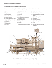
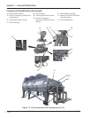
Figure 1-2. Gas Compressor Unit Components .......................................................................................1-4
Figure 2-1. Gas Compressor Unit P&ID ...................................................................................................2-1
Figure 3-1. Rigging and Lifting Points .....................................................................................................3-1
Figure 3-2. Concrete Pad with Compressor Unit Dimensions - Side View ................................................3-5
Figure 3-3. Concrete Pad with Compressor Unit Dimensions - Front View ...............................................3-6
Figure 3-4. Interior Foundation Isolation ................................................................................................3-6
Figure 3-5. Foundation with Housekeeping Pads Dimensions - Top View ................................................3-7
Figure 3-6. Housekeeping Pad Dimension Detail - Top View ...................................................................3-9
Figure 3-7. Level Compressor Unit Using Top Surface of Spherical Washers ............................................3-9
Figure 3-8. Concrete Pad Housekeeping Detail .......................................................................................3-10
Figure 3-9. Maximum Allowable Flange Loads ........................................................................................3-11
Figure 3-10. Installation of Coolers - One Fan Diameter Next to Building ................................................3-12
Figure 3-11. Leg Height ..........................................................................................................................3-13
List of Tables and Figures
Table/Figure Section Number
Section Title Section Number
Section 7 • Warranty and Parts
Warranty Claim Processing ....................................................................................................................7-1
On Site Service Support .........................................................................................................................7-1
Remanufactured Bare Shaft Compressors Process ..................................................................................7-2
Explanation of Rebuild Levels .....................................................................................................7-2
Bare Shaft Compressor Description ............................................................................................7-2
Appendices
Appendix A Torque Specifications ......................................................................................................A
Appendix B Motor (Compressor) General Storage Instructions ..........................................................B
Appendix C Oil Analysis Report ..........................................................................................................C
Appendix D Recommended Header Piping ........................................................................................D
Appendix E Recommended Remote Air Cooled Oil Cooler Piping .......................................................E