


5 – 5
VSG/VSSG • Installation, Operation and Maintenance Manual •Vilter/Emerson • 35391SSG
Section 5 • Maintenance/Service
Oil Charging
WARNING
Avoid skin contact with oil. Wear rubber gloves and a
face shield when working with oil. Failure to comply
may result in serious injury or death.
CAUTION
Do not add oil to the coalescent side of the oil
separator. Failure to comply may result in damage to
equipment.
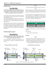
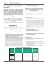
Normal oil level operating range must be maintained for
optimum performance and to prevent damage to equip-
ment. See Figure 4-1. for normal operating levels. There
are a couple of ways to maintain oil, while the compres-
sor unit is in operation and during shutdown.
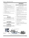
Tool Required:
• Oil Pump, Maximum 2-3 GPM with Motor approved
for Division 1 or Division 2 and with ability to over-
come suction pressure.
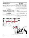
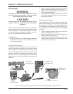
Charging During Operation:
During operation, if the oil level is low, add oil to the
operating compressor through the suction oil charging
valve, see Figure 5-3. Pump oil into the compressor until
the oil level reaches the normal operating level. Watch
this level carefully to maintain proper operation. Never
allow the oil to reach a level higher than the Maximum
Operating Level, since this may impair the operation and
effi ciency.
1. Using a properly selected oil pump, connect oil
pump to suction oil charging valve, see Figure 5-3.
2. Open suction oil charging valve and fi ll oil separator
to Normal Operating Level.
3. Once the Normal Operating Level has been reached,
shut off the oil pump and close the valve. Disconnect
and remove oil pump.
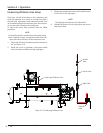
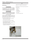
Charging During Shutdown:
During shutdown, if oil is to be added, charging can be
performed through the drain valve located underneath
the oil separator, see Figure 5-3. During shutdown, oil
can be added to the Maximum Non-Operating Level.
For shutdown procedure, see Compressor Unit Isolation
procedure.
1. Using a properly selected oil pump, connect oil
pump to oil separator drain valve.
2. Open oil separator drain valve and fi ll oil separator to
Maximum NON-Operating Level.
3. Once Maximum NON-Operating Level has been
reached, shut off oil pump, close oil separator drain
valve and remove oil pump.
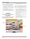
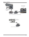
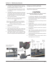
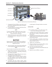
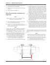
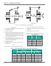
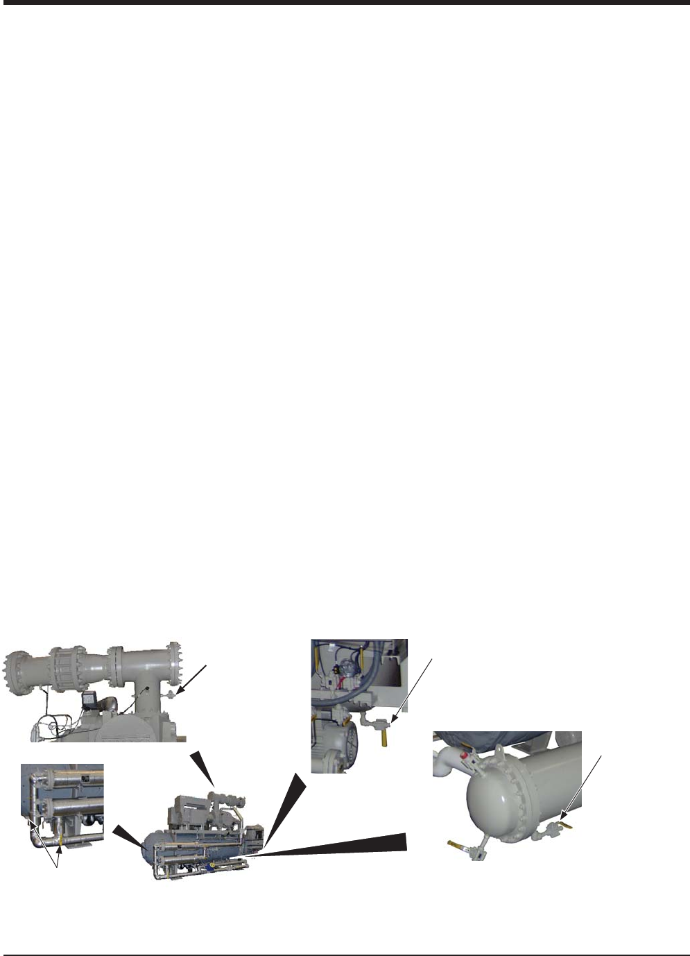
Figure 5-3. Suction Oil Charging Valve, Oil Cooler Drain Valve and Oil Filter Shut-Off Valves
Suction Oil
Charging Valve
View Rotate 180°
Oil Drain Valve
(Oil Separator)
Oil Drain Valve
(Oil Cooler)
View From Back - View Rotate 180°
Oil Filter
Shut-Off Valves