


5 – 24
VSG/VSSG • Installation, Operation and Maintenance Manual •Vilter/Emerson • 35391SSG
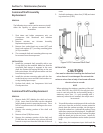
bearing end of the gate rotor support towards the
suction end of the compressor. The compressor
input shaft may have to be rotated to facilitate the
installation of the gate rotor support.
11. Install the roller bearing housing with a new O-ring.
Tighten the bolts to the recommended torque
value.
12. Install the spindle with shims and O-ring, tighten
bolts, see Appendix A. Measure the clearance be-
tween the shelf and blade.
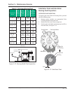
13. Check the clearance between the entire gate ro-
tor blade and the shelf, rotate the gate rotor to
fi nd the tightest spot. It should be between 0.003-
0.004“ (0.076-0.102 mm). Make adjustments, if
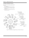
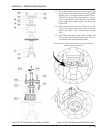
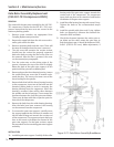
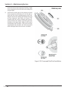
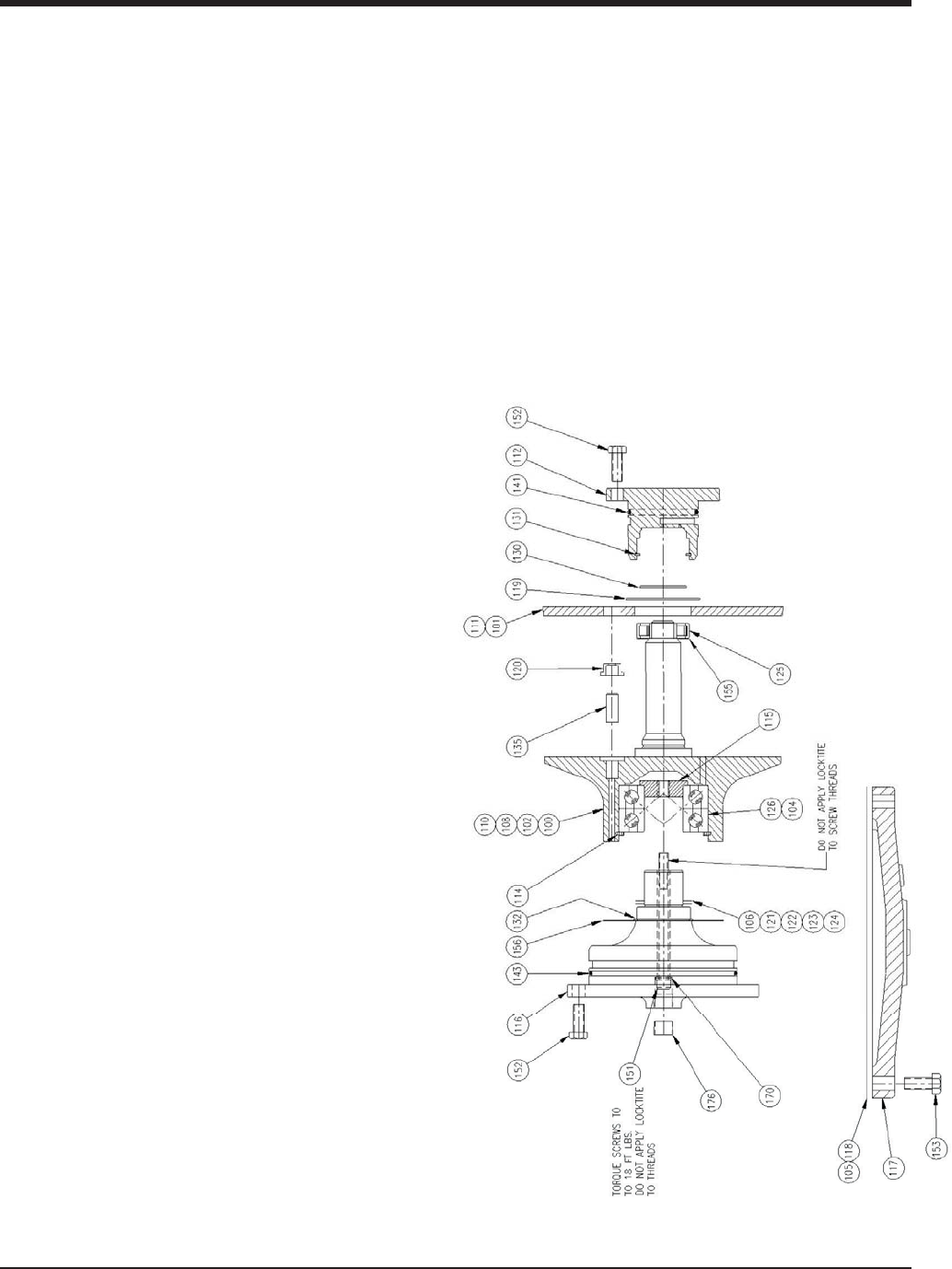
Figure 5-21. Gate Rotor Assembly Breakdown
Gate Rotor Assembly Replacement
(VSG 301-701 Compressors ONLY)
REMOVAL
The removal of the gate rotor assembly for the VSG 301-
701 compressors is similar for the VSG 901- 2101 com-
pressors except that the inner races are secured to the
stationary bearing spindle.
1. Remove center member, see appropriate Drive
Coupling Replacement procedure.
2. Remove the upper bolt from the side cover and in-
stall a guide stud in the hole.
3. Remove remaining bolts and side cover. There will
be some oil drainage when the cover is removed.
4. The side cover that contains the suction strainer
should have the suction line properly supported
before the bolts securing the line to the cover can
be removed. After the line is removed, the cover
can be removed per paragraph B.
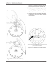
5. Turn the main rotor so the driving edge of the
groove is between the top of the shelf or slightly
below the back of the gate rotor support. At this
point install the gate rotor stabilizing tool.
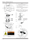
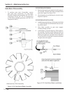
6. Remove plug on the thrust bearing housing. Loosen
the socket head cap screw that is located under-
neath the plug. This secures the inner races of the
thrust bearings to the spindle.
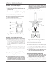
7. Remove bolts that hold the thrust bearing housing
to the compressor. Insert two of the bolts into the
threaded jacking holes to assist in removing the
bearing housing from the compressor. When the
housing is removed, there will be shims between
the spindle and thrust bearings. These control the
clearance between the shelf and gate rotor blades.
These must be kept with their respective parts for
that side of the compressor.
8. Remove the bolts from the roller bearing housing.
After the bolts have been removed, the housing
can be removed from the compressor.
9. To remove the gate rotor support, carefully move
the support opposite the direction of rotation and
tilt the roller bearing end towards the suction end
of the compressor. The compressor input shaft may
have to be turned to facilitate the removal of the
gate rotor support. On dual gate versions, repeat
the procedure for the remaining gate rotor support
assembly.
INSTALLATION
10. Install the gate rotor support. Carefully tilt the roller
Section 5 • Maintenance/Service