


5 – 27
VSG/VSSG • Installation, Operation and Maintenance Manual •Vilter/Emerson • 35391SSG
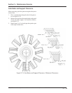
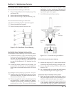
GATE ROTOR THRUST BEARING REMOVAL
For removal of thrust bearings on VSG units:
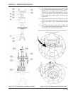
7. Remove bolts (150) from the clamping ring (114),
see Figure 5-26.
8. Remove thrust bearing clamping ring.
9. Remove thrust bearings (126) from housing (113).
For removal of thrust bearings on VSSG units:
10. Remove retaining ring from gate rotor support.
11. Remove bearings from support.
12. Remove bearing retainer from inner race.
Figure 5-26. Gate Rotor Thrust Bearing
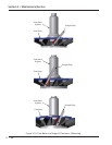
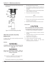
GATE ROTOR THRUST BEARING INSTALLATION
For installation of thrust bearings on VSG and VSSG units:
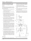
13. Install thrust bearings (126) in the housing so the
bearings are face to face. The larger sides of the in-
ner races are placed together. A light application
of clean compressor lubricating oil should be used
to ease the installation of the bearings into the
housing.
14. Center the bearing retainer ring on housing, use
Loctite® 242-thread locker and evenly tighten the
bolts to the recommended torque value, see Figure
5-27.
For installation of thrust bearings on VSG 301- 701 units:
15. Install retainer in the back of the inner race of one
of the thrust bearings. The back of the inner race is
the narrower of the two sides.
16. The bearing with the retainer should be placed in
the housing fi rst, retainer towards the support.
Install the second bearing. The bearings should be
positioned face to face. This means that the larger
sides of the inner races are placed together. A light
application of clean compressor lubricating oil
should be used to ease the installation of the bear-
ings into the gate rotor support.
17. Install the bearing retaining snap ring.
Figure 5-27. Thrust Bearing Installation
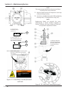
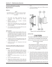
GATE ROTOR ROLLER BEARING REMOVAL
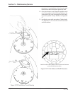
18. Remove the snap ring (131), which retains the roll-
er bearing in the bearing housing, see Figure 5-28.
19. Remove the roller bearing (125) from the bearing
housing (112).
20. Use a bearing puller to remove the roller bearing
race (125) from the gate rotor support (110).
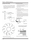
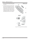
GATE ROTOR ROLLER BEARING INSTALLATION
21. Match up the part numbers on the inner race to
the part numbers outer race. Press the bearing race
(numbers visible) onto the gate rotor support.
22. Install the outer bearing into the bearing housing
so the numbers match the numbers on the inner
race. Install the snap ring retainer in the housing.
Section 5 • Maintenance/Service