


5 – 28
VSG/VSSG • Installation, Operation and Maintenance Manual •Vilter/Emerson • 35391SSG
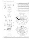
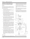
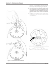
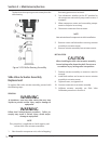
The bevel on the snap ring must face away from the
roller bearing.
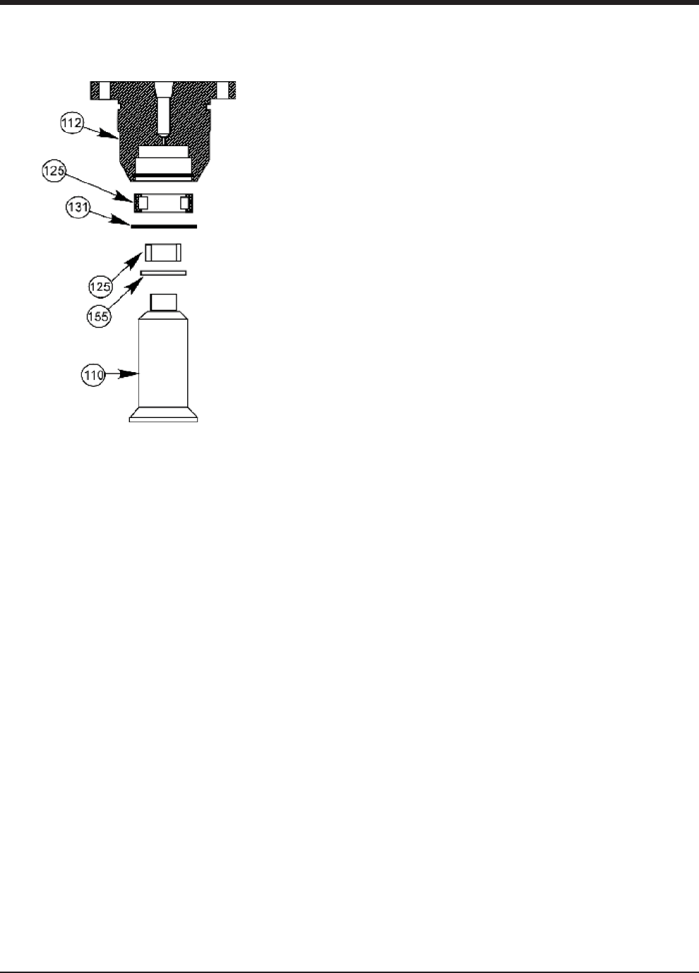
Figure 5-28. Roller Bearing Assembly
Section 5 • Maintenance/Service
Slide Valve Actuator Assembly
Replacement
To replace slide valve actuator assembly, proceed with
the following steps:
REMOVAL
WARNING
At shutdown, open any other valves that may trap
liquids to prevent serious injury and/or damage to
equipment.
WARNING
Follow local lockout/tagout procedure. Failure to
comply may result in serious injury, death and/or
damage to equipment.
NOTE
This procedure is applicable to both capacity and
volume slide valve actuator assemblies.
1. Shut down the compressor unit, refer to Stopping/
Restarting procedure in Section 4.
2. Turn disconnect switches to the OFF position for
the compressor unit and oil pump motor starter, if
equipped.
3. Allow compressor, motor and surrounding compo-
nents to cool prior to servicing.
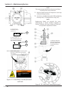
4. Disconnect connectors from actuator.
NOTE
Note orientation of components to aid in installation.
5. Remove screws and lock washers securing actuator
assembly to actuator mount.
6. Remove actuator assembly from actuator mount.
INSTALLATION
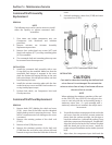
CAUTION
When installing the slide valve actuator assembly,
loosen locking collar down the shaft. Do not use a
screwdriver to pry locking collar into position.
7. Position actuator assembly on mount as noted in
removal.
8. Install lock washers and screws to secure actuator
assembly to actuator mount.
9. Tighten screws, see Appendix A.
10. Connect connectors to actuator assembly.
11. Calibrate actuator assembly, see Slide Valve
Calibration procedure in Section 4.