4 – 12
VSG/VSSG • Installation, Operation and Maintenance Manual •Vilter/Emerson • 35391SSG
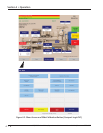
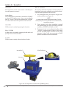
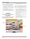
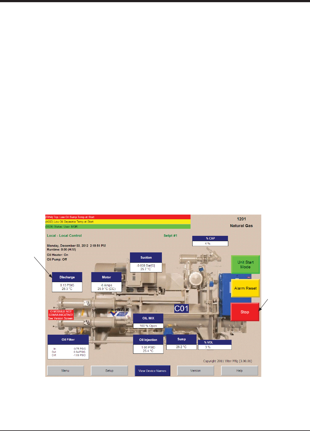
Figure 4-11. PLC Main Screen
Section 4 • Operation
Stop Button
Discharge
Status
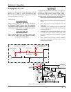
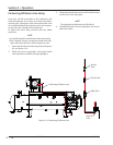
9. Connect purging hose from gas cylinder to suction
oil charging valve.
NOTE
Purging is performed through the suction oil charging
valve so that trapped gas can be pushed out of the
compressor. This will help minimize metal surface
oxidation of the compressor (due to the gas) while not
in service.
10. Purge compressor unit for 4 minutes. Check pres-
sure indicator or discharge status on PLC main
screen to make sure pressure is increasing.
11. Close shut-off valve on purge line while still purging.
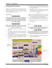
12. Observe discharge pressure of compressor unit
through the PLC main screen.
13. Allow pressure to build to approximately 10 psig in
the compressor unit.
14. Once pressure is reached, stop purging and close
suction oil charging valve.
15. Wait 10 minutes to make sure there are no leaks
and that the pressure is holding.
16. Remove purging hose from suction oil charging
valve.
NOTE
Plugs are installed on bleed valves. Remove and install
plugs prior to and after bleeding. Ensure to keep valves
closed when removing and installing plugs.
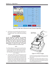
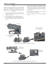
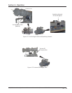
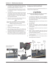
6. Slowly open suction oil charging valve and bleed
remaining pressure in compressor unit to atmo-
sphere, see Figure 4-13. Leave suction oil charging
valve in open position.
7. If equipped with pressure indicator on purge line,
open shut-off valve to pressure indicator.
8. If not equipped with pressure indicator, refer to PLC
main screen for discharge pressure when purging.
PURGE
CAUTION
Do not purge compressor unit with oxygen. Failure to
comply may result in damage to equipment.
CAUTION
Do not allow compressor to spin while purging.
Regulate purging pressure as needed. Failure to
comply may result in damage to equipment.


