


5 – 12
VSG/VSSG • Installation, Operation and Maintenance Manual •Vilter/Emerson • 35391SSG
Section 5 • Maintenance/Service
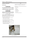
the disc pack.
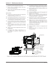
24. Install bolts and locking nuts to secure both disc
packs to center member.
25. Tighten locking nuts.
26. If room is required to install center member, adjust
hub position accordingly. If both the motor and
compressor hubs are straight bores, adjust either
hubs. If one hub is tapered and the other a straight,
adjust the straight bore hub.
27. Using additional supports supporting center mem-
ber. Install bolts and locking nuts to secure center
member to compressor hub.
28. Tighten locking nuts.
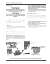
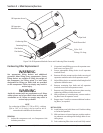
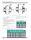
29. Position hubs, ensure distance between face of
both hubs is 5”.
NOTE
If there is waviness with the disc pack installed, adjust
distance accordingly until disc pack is straight.
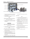
30. Install bolts and locking nuts to secure disc pack to
motor hub.
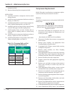
31. Tighten locking nuts, see Table 5-4.
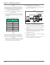
Coupling
Size
Lock Nut
Size
Tightening
Torque
ft-lbs (Nm)
BP38U 5/16-24 22 (30)
BP41U
7/16-20 55 (75)
BP47U 9/16-18 120 (163)
BP54U 9/16-18 120 (163)
BP56U 9/16-18 120 (163)
Table 5-5. Disc Pack Installation Torque
Specifi cations
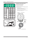
Table 5-4. Hub Clamp Bolt and Set Screw Torque Specifi cations
Coupling
Series/Size
Clamping Bolt Set Screw
# Bolts Size-Pitch
Torque
ft-lbs (Nm)
Size
Torque
ft-lbs (Nm)
BH38U 4 1/4-28 12 (16) 3/8 10 (13)
BH41U
4 5/16-24 23 (31) 3/8 10 (13)
BH47U 4 3/8-24 49 (66) 1/2 20 (27)
BH54U 4 7/16-20 78 (106) 1/2 20 (27)
BH56U 4 1/2-20 120 (163) 5/8 40 (54)
DP42 4 1/2-20 120 (163) 1/2 20 (27)
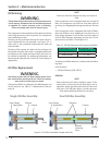
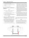
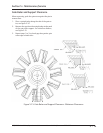
Figure 5-9. Angular Alignment and Parallel Offset
Angular Alignment Parallel Offset