


5 – 13
VSG/VSSG • Installation, Operation and Maintenance Manual •Vilter/Emerson • 35391SSG
Section 5 • Maintenance/Service
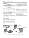
32. Perform hot alignment. Run compressor unit and
allow to warm up completely.
33. Power down compressor unit and re-check align-
ments. Loosen motor mounting nuts to add shims
or to adjust alignments as required.
34. Install coupling guard.
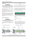
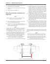
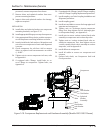
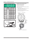
Drive Coupling (Form-Flex BPU)
Center Member and Hub Removal
To remove coupling assembly, proceed with the follow-
ing steps:
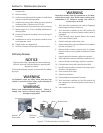
WARNING
At shutdown, open any other valves that may trap
liquids to prevent serious injury and/or damage to
equipment.
WARNING
Follow local lockout/tagout procedure. Failure to
comply may result in serious injury, death and/or
damage to equipment.
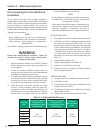
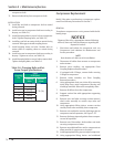
NOTE
Drive coupling type and size can be determined
by the information on the compressor nameplate
when ordering; Order Number and Compressor
Model Number.
1. Shut down the compressor unit, refer to Stopping/
Restarting procedure in Section 4.
2. Turn disconnect switches to the OFF position for
the compressor unit and oil pump motor starter, if
equipped.
3. Allow compressor, motor and surrounding compo-
nents to cool prior to servicing.
4. Remove coupling guard.
5. Remove lock nuts and bolts securing disc pack to
hub on compressor shaft.
6. If additional room is required to remove the center
member, loosen clamping bolts on straight bore
hub(s).
7. Move straight bore hub on shaft as required to al-
low center member removal.
8. Remove lock nuts and bolts securing disc pack to
hub on motor shaft. Remove center member.
9. For straight bore hubs, remove clamping bolts and
hub from shaft.
10. For tapered bore hubs, remove bolt, lock washers,
large washer and hub from shaft.
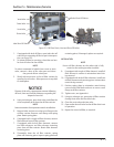
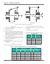
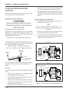
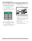
Drive Coupling (Type C Sure-Flex)
Replacement
Drive couplings that are the Type C Sure-Flex type, are
always installed with a C-fl ange between the compres-
sor and motor. The coupling assembly alignments are
built into the design and therefore, should not require
alignment.
NOTE
Drive coupling type and size can be determined
by the information on the compressor nameplate
when ordering; Order Number and Compressor
Model Number.
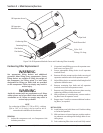
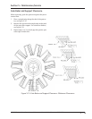
REMOVAL
To remove Type C Sure-Flex coupling, proceed with the
following steps:
WARNING
At shutdown, open any other valves that may trap
liquids to prevent serious injury and/or damage to
equipment.
WARNING
Follow local lockout/tagout procedure. Failure to
comply may result in serious injury, death and/or
damage to equipment.
1. Shut down the compressor unit, refer to Stopping/
Restarting procedure in Section 4.
2. Turn disconnect switches to the OFF position for
the compressor unit and oil pump motor starter, if
equipped.
3. Allow compressor, motor and surrounding compo-
nents to cool prior to servicing.
4. Remove C-fl ange access cover.
NOTE
Mark locations of hubs prior to removal.
5. Loosen set screw in motor hub securing key in
keyway.
6. Loosen clamping bolts securing hub to motor shaft.
7. Pry hub up motor shaft for space to remove cou-
pling sleeve.
8. Remove coupling sleeve from hub.
9. Remove hub and key from motor shaft.
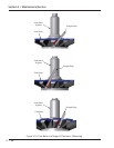
10. Loosen set screw in compressor hub securing key
in keyway.
11. Loosen clamping bolts securing hub from