


4 – 5
VSG/VSSG • Installation, Operation and Maintenance Manual •Vilter/Emerson • 35391SSG
8. Quickly press and release the blue push button on
the actuator one time. This places the actuator in
calibration mode. The red LED will begin fl ashing
rapidly.
CAUTION
DO NOT CONTINUE TO ENERGIZE THE ACTUATO
R
MOTOR AFTER THE SLIDE HAS REACHED THE
MECHANICAL STOP. Doing so may cause mechanical
damage to the motor or shear the motor shaft
key. When the slide has reached the mechanical
stop position, press the button in the center of the
photochopper to release the brake, and thereby
release the tension on the actuator motor.
NOTE
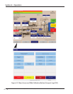
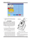
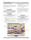
The “Slide calibration” screen on the Control Panel has
a “Current” window, which displays twice the actuator
output voltage. This value, (the % volume and the %
capacity) displayed in the “Current Vol” and Current
Cap” Windows are meaningless until calibration has
been completed.
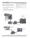
9. Use the DEC button on the Control panel to drive
the slide valve to its minimum “mechanical stop”
position. Do not continue to run the actuator in this
direction after the slide valve has reached the stop.
Doing so may cause damage to the actuator or the
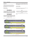
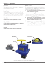
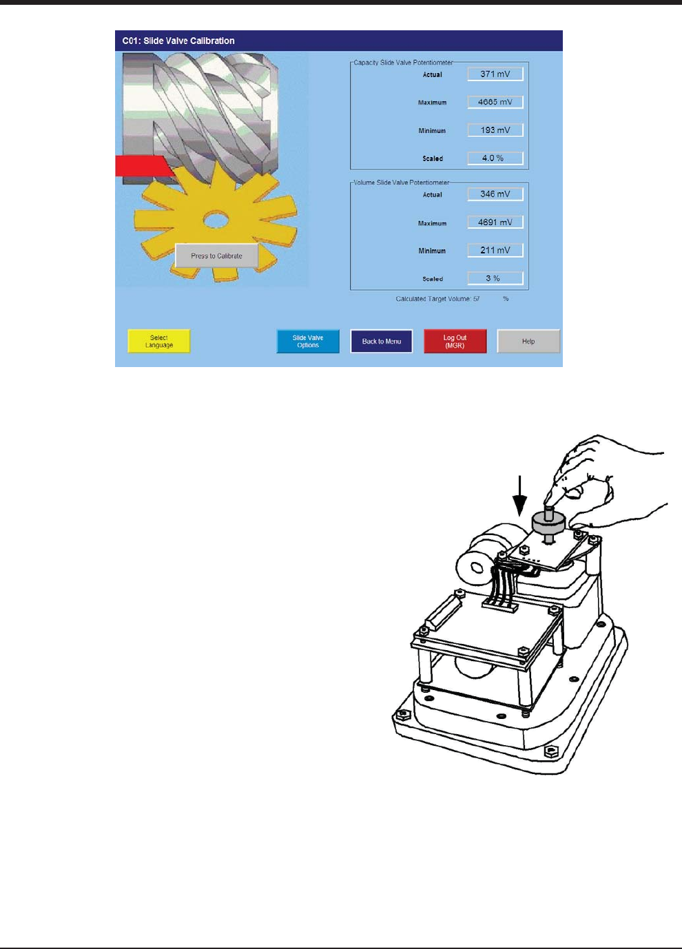
slide valve. Press down on the photo-chopper shaft
to disengage the brake, releasing tension from the
motor mount, see Figure 4-5. Use the INC button
to pulse the actuator to where the slide is just off of
the mechanical stop and there is no tension on the
motor shaft.
10. Quickly press and release the blue button on the ac-
tuator again. The red LED will now fl ash at a slower
rate, indication that the minimum slide valve posi-
tion (zero position) has been set.
Section 4 • Operation
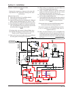
Figure 4-4. Slide Valve Calibration Screen (Compact Logix PLC)
Figure 4-5. Photo-chopper
Press down on
Photo-chopper