


4 – 3
VSG/VSSG • Installation, Operation and Maintenance Manual •Vilter/Emerson • 35391SSG
Section 4 • Operation
• There is an error code fl ashing on the actuator’s
circuit board - an attempt to recalibrate should be
made.
• The range of travel is not correct and the command
shaft travel is physically correct.
• The compressor is pulling high amperage, the cali-
bration of the volume slide should be checked.
• An actuator does not unload below 5%, or an actua-
tor that doesn’t move.
• Something is not working properly such as the actua-
tors, RTDs or transducers.
To calibrate optical actuators, continue with the follow-
ing steps:
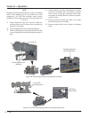
1. Stop compressor unit and allow to cool.
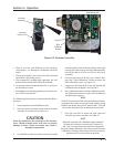
2. Remove screws securing actuator cover to actuator
assembly. As a reference see Figure 4-2.
CAUTION
Wires are attached to the connector on the actuator
cover. Handle actuator cover with care to prevent
damage to wires. Failure to comply may result in
damage to equipment.
3. Carefully lift actuator cover from actuator assembly
and tilt towards Turck connectors. Raise cover high
enough to be able to press the blue calibration but-
ton and be able to see the red LED on the top of
assembly.
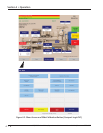
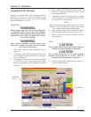
4. On the main screen of the PLC, press “Menu” then
press the “Slide Calibration” button to enter the
slide calibration screen, see Figure 4-3.
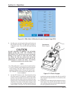
5. Logging on with high-level access will prompt the
Calibrate button to appear, see Figure 4-4.
6. Press Calibrate button to initiate calibration mode.
The Calibrate button turns green and Set Max and
Set Min buttons appear.
NOTE
If the INC (increase) and DEC (decrease) buttons do not
correspond to increase or decrease shaft rotation, swap
the blue and brown wires of the “power cable”. This will
reverse the rotation of the actuator/command shaft.
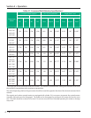
7. Press INC and DEC to move the slide valve and
check for the correct rotation, see Table 4-1.
NOTE
When the actuator is in calibration mode, it outputs
0V when the actuator is running and 5V when it is
still. Thus, as stated earlier, the actuator voltage will
fl uctuate during calibration. After the actuator has been
calibrated, 0V output will correspond to the minimum
position and 5V to the maximum position.
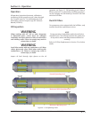
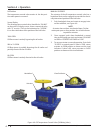
Figure 4-2. Actuator Assembly
Blue
Calibrate
Button
Red LED
Actuator
Plastic Cover
Actuator
Assembly
View Rotate 180°