


5 – 14
VSG/VSSG • Installation, Operation and Maintenance Manual •Vilter/Emerson • 35391SSG
compressor shaft.
12. Remove hub and key from compressor shaft.
INSTALLATION
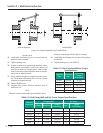
13. Install key and hub on compressor shaft as noted
during removal.
14. Install set screw in compressor hub to secure key in
keyway, see Table 5-6,
15. Install clamping bolts to secure hub on compressor
shaft. Tighten clamping bolts, see Table 5-6,
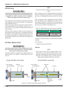
16. Install key and hub on motor shaft as noted during
removal. Allow gap to install coupling sleeve.
17. Install coupling sleeve on hubs. Position hub on
motor shaft on coupling sleeve as noted during
removal.
18. Install set screw in compressor hub to secure key in
keyway. Tighten set screw, see Table 5-6,
19. Install clamping bolts to secure hub to motor shaft.
Tighten clamping bolts, see Table 5-6.
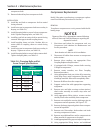
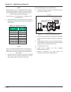
Coupling
Size
Type C
ft-lbs (Nm)
Clamping
Bolts
Key Set
Screw
6 13 (18)
13 (18)
7
13 (18)
8 23 (31)
9 23 (31)
10 50 (68)
11 50 (68)
Table 5-6. Clamping Bolts and Set
Screw Torque Specifi cations
Section 5 • Maintenance/Service
Compressor Replacement
Notify Vilter prior to performing a compressor replace-
ment. See Warranty instructions in Section 7.
REMOVAL
To replace a compressor on a unit, proceed with the fol-
lowing steps:
NOTICE
Dispose of the oil in a appropriate manner following
all Local, State and Federal ordinances regarding the
disposal of used oil.
1. Shut down and isolate the compressor unit, see
Compressor Unit Isolation for Maintenance and
Service procedure.
NOTE
Note location of cables to aid in installation.
2. Disconnect all cables from sensors on compressor
and actuators.
3. Remove drive coupling, see appropriate Drive
Coupling Replacement procedure.
4. If equipped with C-fl ange, remove bolts securing
C-fl ange to compressor.
5. Remove center member, see Drive Coupling
Removal procedure.
6. Using appropriate drain pan, drain oil by removing
drain plugs from under compressor housing and
discharge manifold. Allow oil to completely drain.
7. Remove all oil lines from the compressor.
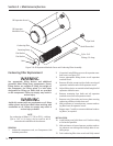
8. Support suction line with appropriate supporting
equipment.
9. Remove nuts and bolts securing suction strainer/
check valve assembly to suction stop valve and
compressor.
10. Using appropriate lifting device, remove suction
strainer/check valve assembly from compressor.
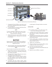
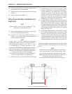
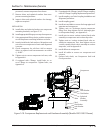
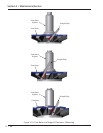
11. Remove nuts and bolts securing discharge pipe to
compressor and oil separator, see Figure 5-10.
12. Remove discharge pipe and gaskets from compres-
sor and oil separator.
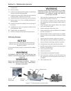
13. Remove nuts, fl at washers, lock washers and studs
securing compressor to frame.
14. Remove any additional lines and/or components to
allow removal of compressor as required.
15. Install appropriate lifting eyes on top of compressor.
16. Using appropriate lifting device and additional