


5 – 10
VSG/VSSG • Installation, Operation and Maintenance Manual •Vilter/Emerson • 35391SSG
Section 5 • Maintenance/Service
with a small clearance over the top.
NOTE
If hub position on shaft does not allow enough room
to install bolts, install bolts and disc pack before
mounting hub on shaft.
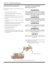
Hubs come in two different types, straight bore and
tapered bore. Tapered bore hubs have additional
hardware. Typically, a compressor will have a
tapered shaft and therefore use a tapered bore hub.
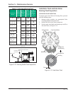
STRAIGHT BORE HUBS
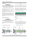
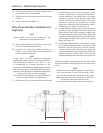
5. For straight bore hubs, install key in keyway of shaft.
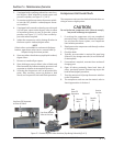
6. Install hub on shaft. If installing straight bore hubs
on motor and compressor shafts, allow 1/16” gap
between the outer face of the hub to the outer face
of the shaft for both hub installation. This will allow
some play when installing the spacer. If installing
a straight bore hub and a taper bore hub, allow a
1/8” gap between the outer face of the straight
bore hub to the outer face of the straight shaft, see
Table 5-3.
7. Install clamping bolts in hub.
8. Tighten clamping bolts, see Table 5-4.
9. Install set screw in hub to secure key.
10. Tighten set screw, see Table 5-4. Repeat steps for
second straight bore hub.
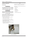
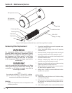
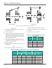
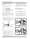
TAPERED BORE HUBS
11. For taper bore hubs, install key in keyway of shaft.
12. Install hub on shaft.
13. If lock washers are being used, install hub cap, lock
washers and bolt on shaft.
14. If locking tab is being used, install hub cap, locking
tab and bolt on shaft.
15. Tighten bolt and draw hub up shaft to a stop.
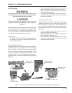
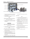
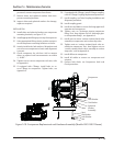
Drive Coupling (Form-Flex BPU) Hub
Installation
On all single screw units, the coupling assembly is
shipped loose and will have to be installed and aligned
on site. This is to allow a check of proper electrical phas-
ing and direction of motor rotation. The motor and
compressor have been aligned from the factory with the
coupling hubs already installed. Using a dial indicator for
aligning is recommended.
NOTE
Drive coupling type and size can be determined
by the information on the compressor nameplate
when ordering; Order Number and Compressor
Model Number.
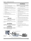
To install the coupling, proceed with the following steps:
WARNING
Follow local lockout/tagout procedure. Failure to
comply may result in serious injury, death and/or
damage to equipment.
1. Ensure disconnect switches are in the OFF position
for the compressor unit and oil pump motor start-
er, if equipped.
2. If hubs are already installed on motor shaft and
compressor shaft, proceed to Drive Center Member
Installation and Alignment procedure.
3. If coupling assembly is already assembled, the lock
nuts are not torqued. Remove lock nuts and bolts
securing hubs to disc packs. Remove both hubs.
Leave the disc packs attached to center member.
4. Clean hub bores and shafts. Remove any nicks
or burrs. If bore is tapered, check for good con-
tact pattern. If bore is straight, measure bore and
shaft diameters to ensure proper fi tment. The keys
should have a snug side-to-side fi t in the keyway
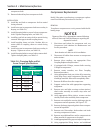
Coupling
Size
Shaft Gap for Tapered
Compressor &
Straight Motor Shaft
Combination
Shaft Gap for Straight
Compressor &
Straight Motor Shaft
Combination
Distance
Between Hub
Faces
BP38U
6.25”
(158.75 mm)
5.125”
(130.18 mm)
5.00”
(127 mm)
BP41U
BP47U
BP54U
BP54U
BP56U
Table 5-3. Shaft and Hub Distances