


3 – 12
VSG/VSSG • Installation, Operation and Maintenance Manual •Vilter/Emerson • 35391SSG
Section 3 • Installation
General Installation Guideline for
Multiple Air Coolers Installed in a
Common Area
NOTE
This general installation guideline applies to all air
coolers on site, whether if they are supplied by or
not supplied by Vilter.
The purpose of this guideline is providing design infor-
mation when multiple air cooled heat exchangers are
installed in a common area. There are two main focal
points of this guideline. One area is free fl ow area which
addresses how much free area is required to prevent air
fl ow “starvation” of the units. The second item provides
a guideline as to how multiple air cooled heat exchang-
ers should be arranged to minimize the potential of hot
air recirculation due to the environment.
FREE FLOW
There are two basic guidelines that we follow to address
free fl ow area when multiple designs are being installed
in a common area.
• Air coolers should be placed at least 1 fan diameter
away from the nearest obstruction. This is based on
the largest fan diameter in the bay of coolers.
• Intake area to the air cooler should have an intake
velocity equal to or below 500FPM as the as the dis-
charge velocity is above 500FPM.
We will look at each rule and provide pictorials and
calculations for each guideline. Let’s assume the follow-
ing coolers are being installed in a common area:
• Cooler 1 - 7’ wide x 10’ long with a 6’ fan moving
55,000CFM of air. Face velocity is 785FPM.
• Cooler 2- 8’ wide x 12’ long with a 7’ fan moving
72,000CFM of air. Face velocity is 750FPM.
• Cooler 3- 10’ wide x 16’ long with a 9’ fan moving
120,000CFM of air. Face velocity is 750FPM.
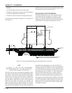
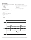
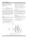
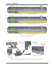
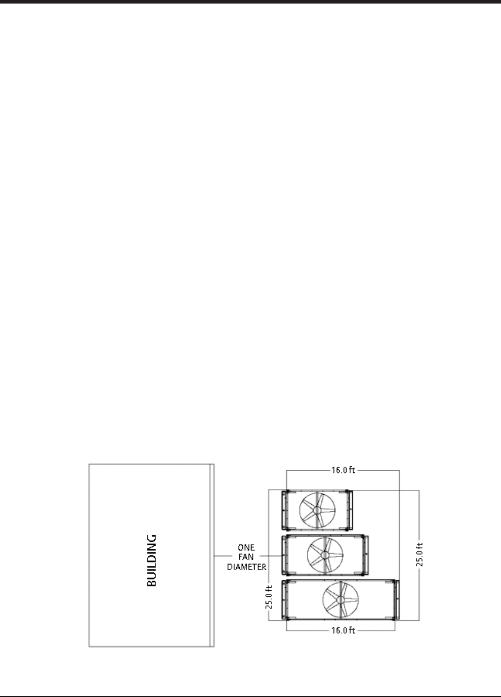
ONE FAN DIAMETER
In order to keep the leg height of the installation to a
minimum we want to install the coolers at least 1 fan di-
ameter from the nearest obstruction. Referring to Figure
3-10, the nearest obstruction is the building.
Based on the information above, the largest fan diame-
ter in the installation is 9ft. Therefore, the coolers should
be placed at least 9’ away from the building.
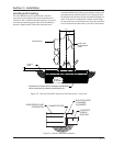
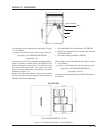
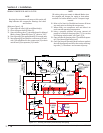
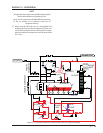
INTAKE VELOCITY
Based on the information above, we are going to solve
for the leg height that will provide an intake velocity of
500FPM. We know the following:
• The total airfl ow of the installation is 247,000CFM
• We have an intake perimeter of 82’ for all 4 sides
based on the cooler placement.
• Our intake velocity guideline is 500FPM
Figure 3-10. Installation of Coolers - One Fan Diameter Next to Building
TOTAL INTAKE PERIMETER = 82 FEET
PREFERRED