


TOC - 4
VSG/VSSG • Installation, Operation and Maintenance Manual •Vilter/Emerson • 35391SSG
Figure 3-12. Installation of Coolers - Next to Buildling ............................................................................3-13
Figure 3-13. Discharge Elevation of Coolers ............................................................................................3-15
Figure 3-14. Cooler Placement and Spacing ............................................................................................3-15
Figure 3-15. Oil Operating Levels ...........................................................................................................3-17
Figure 3-16. Suction Oil Charging Valve, Oil Cooler Drain and Oil Filter Shut-Off Valves ...........................3-17
Figure 3-17. Priming Oil Cooler (Shell & Tube) and Piping .......................................................................3-18
Figure 3-18. Priming Compressor (with Shell & Tube Oil Cooler) and Piping ............................................3-19
Figure 3-19. Priming Remote Oil Cooler and Piping ................................................................................3-20
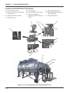
Figure 3-20. Priming Compressor and Oil Filters .....................................................................................3-21
Figure 4-1. Oil Operatiing Levels .............................................................................................................4-1
Figure 4-2. Actuator Assembly ...............................................................................................................4-3
Figure 4-3. Menu Screen and Slide Calibraiton Button (Compact Logix PLC) ...........................................4-4
Figure 4-4. Slide Valve Calibraiton Screen (Compact Logix PLC) ..............................................................4-5
Figure 4-5. Photo-chopper .....................................................................................................................4-5
Figure 4-6. Oil Temperature Control Valve (Oil Mixing Valve) ..................................................................4-8
Figure 4-7. PLC Main Screen ...................................................................................................................4-9
Figure 4-8. Suction Bypass Valve and Equalizing Solenoid .......................................................................4-10
Figure 4-9. Suction Oil Charging Valve and Discharge Bleed Valve ..........................................................4-10
Figure 4-10. Customer Purge Line ..........................................................................................................4-11
Figure 4-11. PLC Main Screen .................................................................................................................4-12
Figure 4-12. Suction Bypass Valve and Equalizing Solenoid .....................................................................4-13
Figure 4-13. Suction Oil Charging Valve .................................................................................................4-13
Figure 4-14. Coalescing Oil Return Line ..................................................................................................4-14
Figure 5-1. Suction Bypass Valve (Manual) Location (1 of 2) ....................................................................5-2
Figure 5-1. Suction Bypass Valve (Equalizing Solenoid) Location (2 of 2) .................................................5-3
Figure 5-2. Oil Analysis Kit ......................................................................................................................5-4
Figure 5-3. Suction Oil Charging, Oil Cooler Drain Valve and Oil Filter Shut-Off Valves ............................5-5
Figure 5-4. Oil Filter Assemblies (Single and Dual) ..................................................................................5-6
Figure 5-5. Oil Filter Drain, Vent and Shut-Off Valves ..............................................................................5-7
Figure 5-6. Oil Separator Manhole Cover and Coalescing Filter Assembly ................................................5-8
Figure 5-7. Oil Pump Strainer and Drain Valve ........................................................................................5-9
Figure 5-8. Hub Distance (Axial Spacing) ................................................................................................5-11
Figure 5-9. Angular Alignment and Parallel Offset ..................................................................................5-12
FIgure 5-10. Compressor Replacement and Hardware Assembly (Models 2401-3001 Shown) ................5-15
FIgure 5-11. Bearing Axial Float Inspection (Compressor) .......................................................................5-16
FIgure 5-12. Bearing Radial Float Inspection (Compressor) .....................................................................5-17
FIgure 5-13. Gate Rotor Float .................................................................................................................5-17
FIgure 5-14. Gate Rotor Bearing Float .....................................................................................................5-18
FIgure 5-15. Gate Rotor and Support Clearance - Minimum Clearances ..................................................5-19
FIgure 5-16. Gate Rotor and Support Clearance - Measuring ...................................................................5-20
FIgure 5-17. Gate Rotor Assembly Removal and Tools ............................................................................5-22
FIgure 5-18. Gate Rotor Assembly Removal ............................................................................................5-22
FIgure 5-19. Gate Rotor Assembly and Tools ...........................................................................................5-23
FIgure 5-20. Gate Rotor and Shelf Clearance ...........................................................................................5-23
FIgure 5-21. Gate Rotor Assembly Breakdown ........................................................................................5-24
FIgure 5-22. Gate Rotor Thrust Bearing ..................................................................................................5-25
FIgure 5-23. Gate Rotor and Shelf Clearance ...........................................................................................5-25
FIgure 5-24. Gate Rotor Blade Assembly .................................................................................................5-26
FIgure 5-25. Gate Rotor Blade Installation ..............................................................................................5-26
FIgure 5-26. Gate Rotor Thrust Bearing ..................................................................................................5-27
FIgure 5-27. Thrust Bearing Installation ..................................................................................................5-27
FIgure 5-28. Roller Bearing Assembly .....................................................................................................5-28
FIgure 5-29. Command Shaft Seal ..........................................................................................................5-29
FIgure 5-30. Command Shaft Seal Installation ........................................................................................5-30
List of Tables and Figures
Table/Figure Section Number