


4 – 6
VSG/VSSG • Installation, Operation and Maintenance Manual •Vilter/Emerson • 35391SSG
Compressor
Model
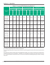
Command Shaft Rotation No. of Turns/Rotation Angle/Slide Travel
Capacity Volume Capacity Volume
INC DEC INC DEC Turns Degrees Travel Turns Degrees Travel
VSSG 291
VS
SG 341
VSSG 451
VSSG 601
CW CCW CW CCW 0.91 328 3.568” 0.52 187 2.045”
VSG 301
VSG361
VSG 401
CW CCW CW CCW 0.80 288 3.141” 0.45 162 1.767”
VSG 501
VSG 601
VSG 701
CCW CW CCW CW 0.91 328 3.568” 0.52 187 2.045”
VSG 751
VSG 901
CCW CW CCW CW 1.09 392 4.283” 0.63 227 2.473”
VSG 791
VSG 891
VSG 1051
VSG 1201
VSG 1301
CCW CW CCW CW 1.22 439 4.777” 0.74 266 2.889”
VSG 1551
VSG 1851
VSG 2101
CCW CW CCW CW 1.48 533 5.823” 0.87 313 3.433”
VSG 2401
VSG 2601
VSG 2801
VSG 3001
CCW CW CCW CW 1.80 648 7.072” 1.36 490 5.341”
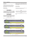
Table 4-1. Command Shaft Rotation Specifi cations*
Section 4 • Operation
*The large gear on the command shaft has 50 teeth. The teeth are counted when moving the command shaft from
the minimum stop position to the maximum stop position.
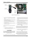
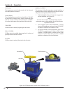
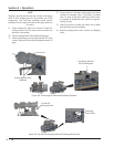
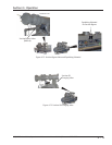
The manual operating shaft on the gear motor should be turned the opposite direction of the desired command shaft
rotation.
The capacity and volume control motors are equipped with a brake, if it is necessary to operate the control motors
manually, the brake must be disengaged. The brake can be disengaged by pushing on the motor shaft on the cone
end. The shaft should be centered in its travel. Do not use excessive force manually operating the motor or damage
may result.