


5 – 21
VSG/VSSG • Installation, Operation and Maintenance Manual •Vilter/Emerson • 35391SSG
Gate Rotor Assembly Replacement
(All VSG & VSSG Compressors Except
VSG 301-701 Compressors)
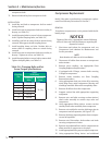
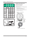
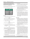
The following table lists the gate rotor tool sets needed
to remove and install gate rotor assemblies.
Table 5-9. Gate Rotor Tool Sets
Model Tool Set VPN
VSSG 291-601 A25205B
VSG 301-401 N/A
VSG 501-701 A25205B
VSG 751-1301 A2520 5C
VSG 1551-2101 A25205E
VSG 2401-3001 A25205F
REMOVAL
1. Remove center member, see appropriate Drive
Coupling Replacement procedure.
NOTE
All parts must be kept with their appropriate side
and not mixed when the compressor is reassembled.
2. Remove two upper bolts from side cover
3. Install guide studs in holes.
NOTE
There will be some oil drainage when the cover is
removed.
4. Remove remaining bolts and side cover.
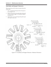
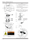
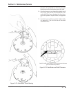
5. Turn main rotor so a driving edge of any one of the
main rotor grooves is even with the back of the gate
rotor support.
NOTE
The gate rotor stabilizer is designed to hold the gate
rotor support in place and prevent damage to the
gate rotor blade as the thrust bearings and housing
is being removed.
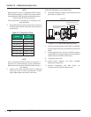
6. Insert gate rotor stabilizer. The side rails are not re-
quired on VSSG 291 thru 601. For the VSG 751 thru
901 and VSG 1051 thru 1301 compressors, use the
side rails and assemble to the gate rotor stabilizer
as stamped. For the VSG 1551 thru 2101, use the
side rails and assemble to the gate rotor stabilizer.
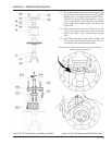
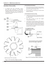
7. Remove hex head bolts and socket head bolts from
thrust bearing cover.
8. Re-install two bolts into the threaded jacking holes
to assist in removing thrust bearing cover. Retain
the shim pack.
9. Hold gate rotor support with a suitable wrench on
the fl ats provided near the roller bearing housing.
10. Remove the inner retainer bolts and retainer.
11. To remove the thrust bearing housing, install thrust
bearing removal and installation tool with smaller
puller shoe. Turn the jacking screw clockwise. The
thrust bearings and housing assembly will be pulled
off the shaft and out of the frame.
12. Remove bolts from roller bearing housing.
13. Re-install two bolts into jack bolt holes provided in
housing to aid in removal.
14. To remove the gate rotor support, carefully move
support in the opposite direction of rotation and
tilt roller bearing end towards the suction end of
the compressor. The compressor input shaft may
have to be turned to facilitate the removal of the
gate rotor support. On dual gate compressor units,
repeat the procedure for the remaining gate rotor
support assembly.
INSTALLATION
15. Install gate rotor support by carefully tilting the
roller bearing end of the gate rotor support towards
the suction end of the compressor. The compressor
input shaft may have to be rotated to facilitate the
installation of the gate rotor support. Install gate
rotor stabilizer. The gate rotor stabilizer (901) will
hold the gate rotor support in place as the thrust
bearing housing is being installed. If the gate rotor
support is not restricted from moving, the gate ro-
tor blade may be damaged.
16. Install the roller bearing housing (112) with a new
O-ring (141).
17. Tighten bolts (152), see Appendix A.
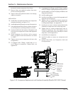
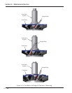
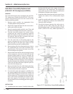
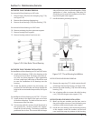
18. When installing the thrust bearing housing (113), a
new O-ring (142) must be used when the housing
is installed, see Figure 5-19. Lubricate the outside
of the housing and bearings with clean compres-
sor oil to aid in the installation. Due to the fi t of the
bearings on the gate rotor shaft, the thrust bearing
removal and installation tool with the pusher shoe
must be used. Turn the jacking screw clockwise.
This will push the thrust bearings onto the shaft
and push the housing assembly into the frame.
Install the inner retainer (115) and bolts (151) us-
ing Loctite® 242 thread locker. Tighten bolts, see
Appendix A.
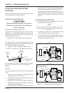
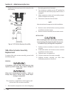
19. Set clearance between gate rotor blade and shelf.
20. Place a piece of 0.003”-0.004” shim stock between
gate rotor blade and shelf.
Section 5 • Maintenance/Service