


2 – 2
VSG/VSSG • Installation, Operation and Maintenance Manual •Vilter/Emerson • 35391SSG
suction. The discharge temperature of the compressor
must be kept a minimum of 30°F (or 17°C) above the dis-
charge gas dew point to prevent the condensing of liq-
uids in the oil separator. The oil separator shell and legs
must be insulated when the gas stream has a high prob-
ability of having condensables.
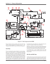
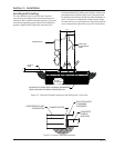
Oil in the gas compressor unit serves three primary pur-
poses. They are compressor lubrication, sealing clear-
ances between moving parts, and heat removal result-
ing from heat of compression and friction. Initially, oil
fl ow is driven by a mechanical gear pump (7). Once the
system reaches design conditions, the oil pump is shut
off and oil fl ow is maintained by differential pressure in
the gas system.
As the oil is separated from the gas in the oil separator,
it is pumped or syphoned through an oil cooler (9), then
fi ltered through a single (11) or dual oil fi lters (15) and
back to the injection port of the compressor (14). The
standard oil cooler is a shell and tube water cooled heat
exchanger (9). The other option is to air cool oil remotely
through a fi nned fan heat exchanger (8).
Furthermore, to collect oil from the coalescing side of
the oil separator (12), a line is installed between the oil
separator and the compressor. By opening the shut-off
valve (6), this will allow oil dripping off the coalescing fi l-
ters to be fed back to the compressor. In addition, the oil
cooler (8 or 9) is piped in parallel to the oil temperature
control valve (oil mixing vlave) (10), which acts as a by-
pass valve.
On units with a full-time oil pump, oil pressure is regu-
lated by the oil pressure regulator (12). It controls up-
stream pressure to the compressor bearings and should
be adjusted to hold the oil pressure at 20 psig above suc-
tion pressure. Excess oil not required for bearing lubrica-
tion is passed through the regulator and back into the oil
separator (13).
This is a continuous cycle.
Control System
The gas compressor unit is controlled by a Programmable
Logic Controller (PLC) panel. This PLC panel’s main func-
tion is to control the gas compression system from the
data that it receives from the sensors around the unit.
Refer to Compact Logix PLC manual (35391CL) for addi-
tional information.
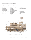
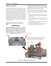
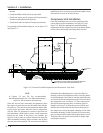
RTDs and Pressure Transducers
Resistance Thermometers (RTDs) and pressure trans-
ducers are instruments used to measure temperatures
and pressures at specifi c locations on the gas compressor
unit, see Figure 1-2. Gas Compressor Unit Components.
RTDs are typically mounted on the suction pipe, dis-
charge pipe, oil separator and oil fi lter outlet pipe.
Pressure transducers are typically mounted on the block
and bleed assembly and directly on the suction pipe. The
pressure transducers measure suction pressure, inlet
and outlet oil pressure, and oil separator pressure.
Section 2 • Theory of Operation