


5 – 11
VSG/VSSG • Installation, Operation and Maintenance Manual •Vilter/Emerson • 35391SSG
Section 5 • Maintenance/Service
16. If locking tab is being used, bend locking tabs in
gap towards shaft and around bolt.
17. Install set screw in hub cap to secure key in keyway
of shaft.
18. Tighten set screw, see Table 5-4.
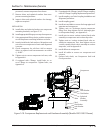
Drive Center Member Installation and
Alignment
NOTE
Always adjust motor to the compressor. The
compressor is aligned to the frame.
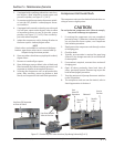
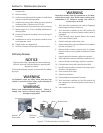
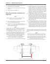
19. Adjust motor position as needed to obtain a dis-
tance of 5” between both hub faces.
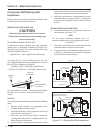
20. Soft Foot. The motor must sit fl at on its base (+/-
0.002”). Any soft foot must be corrected prior to
center member installation.
NOTE
If the driver or driven equipment alignment
specifi cation is tighter than these recommendations,
the specifi cation should be used. Also, be sure
to compensate for thermal movement in the
equipment. The coupling is capable of approximately
four time the above shaft alignment tolerances.
However, close alignment at installation will provide
longer service with smoother operation.
The fl ex disc pack is designed to an optimal thickness
and is not to be used for axial adjustments.
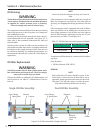
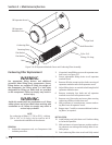
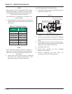
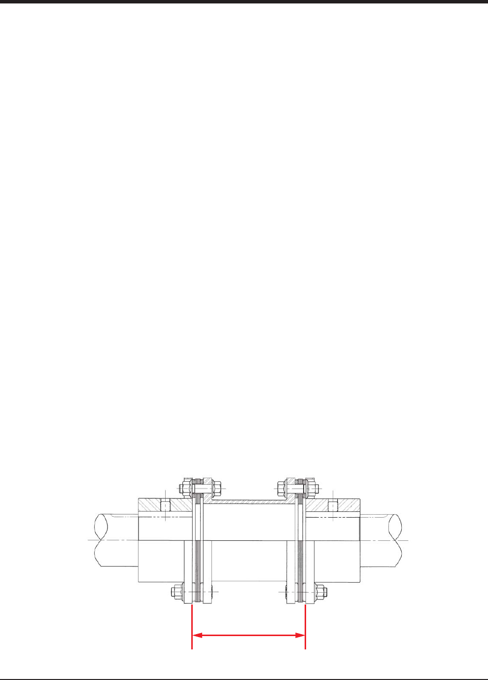
21. Axial Spacing. The axial spacing of the shafts should
be positioned so that the fl ex disc packs are fl at
when the equipment is running under normal op-
erating conditions. This means there is a minimal
amount of waviness in the fl ex disc pack when
viewed from the side. This will result in a fl ex disc
pack that is centered and parallel to its mating
fl ange faces. Move the motor to obtain the correct
axial spacing, see Table 5-3 and Figure 5-8.
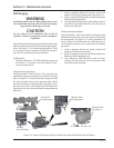
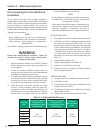
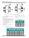
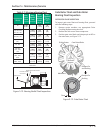
22. Angular Alignment. Rigidly mount a dial indicator on
one hub or shaft, reading the face of the other hub
fl ange. Rotate both shafts together, making sure
the shaft axial spacing remains constant. Adjust the
motor by shimming and/or moving so that the indi-
cator reading is within 0.002” per inch of coupling
fl ange, see Figure 5-9.
23. Parallel Offset. Rigidly mount a dial indicator on one
hub or shaft, reading the other hub fl ange outside
diameter. Indicator set-up sag must be compen-
sated for. Rotate both shafts together. Adjust the
equipment by shimming and/or moving so that the
indicator reading is within 0.002” per inch of the
axial length between fl ex disc packs, see Figure 5-9.
With the coupling in good alignment the bolts will fi t
through the holes in the fl anges and the disc packs more
easily.
NOTE
All bolt threads should be lubricated. A clean motor
oil is recommended. On size 226 and larger, a link
must be put on bolt fi rst. Remove the disc pack
alignment bolt. Proceed to mount the second disc
pack to the other hub in the same way.
Ensure that the beveled part of the washer is against
Hub Distance
Figure 5-8. Hub Distance (Axial Spacing)