


5 – 26
VSG/VSSG • Installation, Operation and Maintenance Manual •Vilter/Emerson • 35391SSG
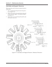
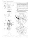
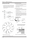
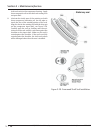
GATE ROTOR BLADE REMOVAL
2. Remove the snap ring and washer from the gate ro-
tor assembly. Lift gate rotor blade assembly off the
gate rotor support, see Figure 5-24.
3. Check damper pin and bushing for excessive wear.
Replace if required.
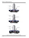
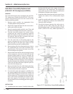
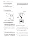
GATE ROTOR BLADE INSTALLATION
4. Install damper pin bushing (120) in gate rotor blade
(111) from the back side of the blade. Be sure bush-
ing is fully seated.
5. Place blade assembly on gate rotor support.
Locating damper over pin.
6. Install washer (119) and snap ring (130) on gate ro-
tor assembly. The bevel on the snap ring must face
away from the gate rotor blade. After the gate rotor
blade and support are assembled, there should be
a small amount of rotational movement between
the gate rotor and support.
Figure 5-25. Gate Rotor Blade Installation
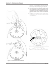
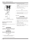
Gate Rotor Disassembly
1. To perform gate rotor disassembly, remove
gate rotor from compressor, see Gate Rotor
Assembly Replacement procedure (All VSG-VSSG
Compressors Except VSG 301-701 Compressors)
or Gate Rotor Assembly procedure (VSG 301-701
Compressors ONLY).
Section 5 • Maintenance/Service
Figure 5-24. Gate Rotor Blade Assembly