


2 – 1
VSG/VSSG • Installation, Operation and Maintenance Manual •Vilter/Emerson • 35391SSG
Section 2 • Theory of Operation
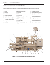
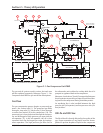
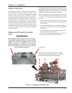
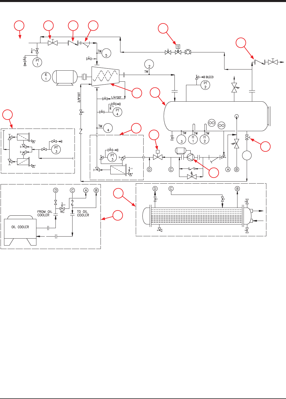
The gas and oil systems work in unison, but each one
will be explained separately. Reference Figure 3 - Gas
Compressor Unit P&ID for gas and oil fl ow descriptions.
Gas Flow
The gas compression process begins as processed gas
enters the suction inlet (1). The processed gas fl ows
through a stop valve (2), check valve (3) then through
a suction line strainer (4) to the compressor (14). The
processed gas is then pressurized through the compres-
sor and discharged as high pressure gas vapor into the
oil separator (13). In the oil separator, the oil is then
separated from the discharged gas vapor by impinge-
ment separation. The high pressure gas fl ows out to
the aftercooler and scrubber for cooling while the oil is
pumped or syphoned back to the compressor.
Moreover, check valves (3) and (6) are provided between
the oil separator to prevent gas vapor or liquid from fl ow-
ing back to the compressor during shutdown periods.
An equalizing line is also installed between the high
pressure side (oil separator) and low pressure side (suc-
tion) to allow .
Oil Life and Oil Flow
The life of the oil is directly affected by the quality of the
gas. Proper separation of any liquids must be accom-
plished to prevent droplets of liquid at the compressor
OIL SEPARATOR
OPTIONAL DUAL OIL FILTERS
STANDARD SINGLE
OIL FILTER
COMPRESSOR
FILTER
FILTER
DRAIN
DRAIN
BLEED
FILTER
BLEED
DRAIN
DRAIN
BLEED
SUCTION GAS
1/4” OIL CHARGING
1/4”
100#
DISCHARGE
STOP VALVE
MOTOR
BLEED
MOTOR
M
PUMP
CHECK
VALVE
TE
TE
TE
TE
FG
1
OPTIONAL REMOTE AIR COOLED OIL COOLER
STANDARD WATER COOLED OIL COOLER
OIL COOLER
DRAIN
VENT
OIL
DRAIN
Figure 2-1. Gas Compressor Unit P&ID
1 2 3 4
14
13
6
15
9
10
8
7
11
12
5