


5 – 18
VSG/VSSG • Installation, Operation and Maintenance Manual •Vilter/Emerson • 35391SSG
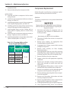
NOTE
Measurements can be an additional 0.020” higher
than fl oat dimensions on Table 5-8. If measurement
is an additional 0.030” greater than fl oat dimensions,
contact Vilter for further assistance.
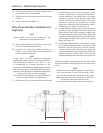
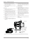
Total movement of damper pin in bushing is the
gate rotor fl oat.
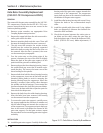
4. Using dial indicator, take measurement of gate ro-
tor fl oat. Measurement should not exceed values as
noted above.
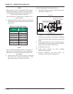
Table 5-8. Gate Rotor Float
Model
Float
in. (mm)
VSSG 291-601 0.045 (1.143)
VSG 301-401
0.045 (1.143)
VSG 501-701 0.045 (1.143)
VSG 751-901 0.055 (1.397)
VSG 1051-1301 0.060 (1.524)
VSG 1551-2101 0.060 (1.524)
VSG 2401-3001 0.060 (1.524)
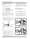
NOTE
Some movement between blade and support is
necessary to prevent damage to the compressor
blade; however at no time should the blade uncover
the support.
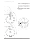
5. Inspect main rotor and gate rotor for abnormal
wear due to dirt or other contaminants. If dam-
aged, replace gate rotor and/or main rotor.
Section 5 • Maintenance/Service
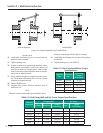
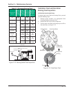
GATE ROTOR BEARING FLOAT INSPECTION
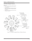
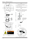
6. Using dial indicator, position a dial indicator on the
gate rotor, see Figure 5-14.
Side View
Wooden block to prevent
damage to gate rotor blade.
Direction of rotor movement.
Axial force at gate rotor to not
exceed 100 lbs.
Gate rotor bearing float being measured.
Use bolt for fulcurm.
Rigidly attach dial indicator.
Applied
Force
Figure 5-14. Gate Rotor Bearing Float
7. Use a lever arm pivoting on a bolt with a small block
of wood against the gate rotor blade to protect the
blade.
8. Gently apply pressure to lever and take measure-
ment. Maximum amount of gate rotor bearing fl oat
should not exceed 0.002” (0.051 mm).
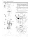
9. Install gate rotor cover.
10. Install center member, see Drive Coupling
Replacement procedure.
11. Perform compressor unit leak check, see
Compressor Unit Leak Check procedure.