


3 – 16
VSG/VSSG • Installation, Operation and Maintenance Manual •Vilter/Emerson • 35391SSG
Section 3 • Installation
Initial Oil Charging
Using Non -Vilter Oils
CAUTION
Do not mix oils. Failure to comply may result in
damage to equipment.
NOTICE
Vilter does not approve non-Vilter oils for use with
Vilter compressors. Use of oils not specifi ed or
supplied by Vilter will void the compressor warranty.
Due to the need for adequate lubrication, Vilter recom-
mends only the use of Vilter lubricants, designed spe-
cifi cally for Vilter compressors. With extensive research
that has been performed, we are able to offer gas com-
pression lubricating oils. Use of oil not specifi ed or sup-
plied by Vilter will void the compressor warranty.
Please contact your local Vilter representative or the
Home Offi ce for further information.
Unit Oil Charging and Priming
WARNING
Avoid skin contact with oil. Wear rubber gloves and a
face shield when working with oil. Failure to comply
may result in serious injury or death.
NOTICE
Failure to follow these instructions will result in
bearing damage and compressor seizing and will void
any and all warranties that may apply.
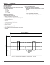
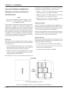
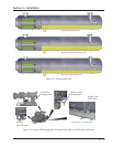
Typically, the compressor unit is shipped from Vilter with
no oil charge. The normal operating level is between the
two sight glasses on the oil separator, see Figure 3-15.
Refer to supplied GA drawing for unit specifi c oil charge
requirement.
For regular oil charging and draining procedures, see
Section 5.
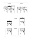
Tool Required:
• Oil Pump, Maximum 2-3 GPM with Motor approved
for Division 1 or Division 2 and with ability to over-
come suction pressure.
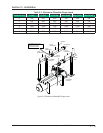
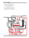
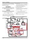
(Reference Figure 3-17)
1. At initial start up, compressor unit must be off and
depressurized prior to initial oil charging.
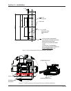
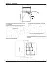
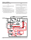
2. Using a properly selected oil pump, connect oil
pump to oil separator drain valve (4). For oil separa-
tor drain valve location, see Figure 3-16.
3. Open oil separator drain valve (4) and fi ll oil separa-
tor (3) to Maximum NON-Operating Level.
4. Once Maximum NON-Operating Level has been
reached, shut off oil pump, close oil separator drain
valve (4) and remove oil pump.
5. If equipped with remote oil cooler, refer to Priming
Remote Oil Cooler and Piping procedure.
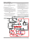
PRIMING OIL COOLER (SHELL AND TUBE) AND PIPING
If equipped with a shell and tube oil cooler, continue
with the following steps:
6. Close shut-off valve (8) at oil fi lter inlet. Do the same
for second oil fi lter, if equipped with dual oil fi lters.
For shut-off valve location, see Figure 3-16.
7. Open oil bypass shut-off valve (5). For oil cooler by-
pass valve location, see Figure 3-16.
8. Energize compressor unit.
9. Close oil mixing valve (oil temp. control valve) (7) via
control panel. In Manual Mode, change “Manually
Open (%)” value to “0”.
NOTE
The oil cooler is considered primed when the oil
level in the separator is constant.
10. Run the oil pump (6) twice for 1-2 minutes. Repeat
this step until the oil level (9) is constant.
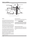
Pressure Testing
CAUTION
Do not hydro test compressur unit. Failure to comply
may result in damage to equipment.
CAUTION
The compressor unit along with other system units
contain many components with various pressure
ratings. Pressure relief protection provided considers
the design pressure of a system components.
Before replacing a pressure relief valve with a relie
f
valve having a higher presure setting, all system
components must be evaluated for acceptability.
Pressure test in compliance with Chapter VI of the ASME
B31.3 Process Piping Code.