


3 – 18
VSG/VSSG • Installation, Operation and Maintenance Manual •Vilter/Emerson • 35391SSG
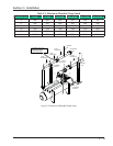
OIL
PT
004
FG
001
TE
001
PT
001
BLEED
BLEED
DRAIN
PT
002
BLEED
TE
004
QE
101
QE
102
QE
103
TE
005
1000W 1000W 1000W
LG
001
LG
002
OIL CHARGE
TE
002
COMPRESSOR
MOTOR
OIL COOLER
MOTOR
OIL PUMP
OIL FILTER
OIL FILTER
COALESCING OIL RETURN LINE
PRESSURE
EQUALIZING LINE
SUCTION INLET
DISCHARGE OUTLET
OIL MIXING
VALVE
DRAIN
CLOSE
CLOSE
CLOSE
OPEN
OIL SEPARATOR
DRAIN
DRAINVENT
COOLING
WATER
DISCHARGE OUTLET
SUPPLY
RETURN
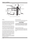
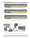
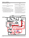
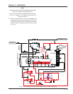
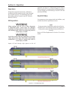
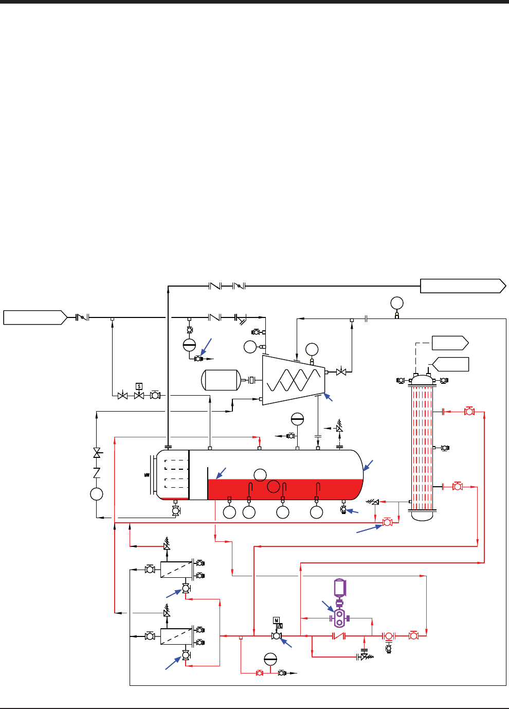
Figure 3-17. Priming Oil Cooler (Shell & Tube) and Piping
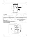
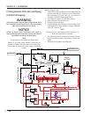
PRIMING COMPRESSOR AND OIL FILTERS
NOTE
Running the compressor oil pump at this point will
help lubricate the compressor bearings and shaft
seal surfaces.
(Reference Figure 3-19)
11. Open shut-off valve(s) (8) at oil fi lter inlet(s).
12. Close oil bypass shut-off valve (5).
13. Open oil mixing valve (7) via control panel. In Manual
Mode, change “Manually Open (%)” value to “100”.
14. Run oil pump (6) for approximately 20 seconds only.
15. Stop oil pump (6) and wait for a minimum of 30 min-
utes. This will allow oil in the compressor (2) to drain
and oil level (9) in separator (2) to settle.
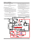
NOTE
Oil mixing valve can remain in Manual Mode since
the setpoint will change the mode to Auto when
reached. For further details, see PLC Compact Logix
manual.
16. Refer to Pre Start-Up Checklist and ensure all items
are ready prior to starting the compressor.
17. When ready, run compressor unit and allow it to
reach normal operating temperature.
18. Using a properly selected oil pump, connect oil
pump to suction oil charging valve (1). For suction
oil charging valve location, see Figure 3-16.
19. Open suction oil charging valve (1) and fi ll oil separa-
tor (3) to Normal Operating Level.
20. Once the Normal Operating level has been reached,
shut off the oil pump and close the suction oil charg-
ing valve (1). Disconnect and remove oil pump.
Section 3 • Installation
3
8
8
7
6
5
1
2
4
9