


5 – 3
VSG/VSSG • Installation, Operation and Maintenance Manual •Vilter/Emerson • 35391SSG
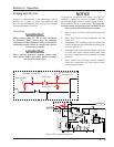
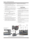
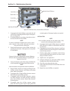
2. If equipped with equalizing solenoid to control suc-
tion by-pass, allow solenoid to remain open until
pressures equalize, see Figure 5-1 (2 of 2).
3. Turn motor and oil pump starter disconnect switch-
es into the OFF position. Lockout/tagout discon-
nect switches.
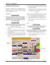
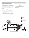
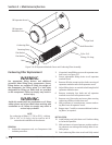
4. If equipped with manual suction by-pass valve and
it is not open, open suction by-pass valve to allow
oil separator pressure to vent to low-side system
pressure, see Figure 5-1 (1 of 2). Close suction by-
pass valve when complete.
5. Isolate the compressor unit by closing all valves to
the house system. Lockout/tagout valves.
NOTE
If drain valves are installed on suction and discharge
headers, open these valves too to remove build up
of liquid during shut-down periods.
6. Open any other valves that may trap liquid. Lockout/
tagout valves.
7. Recover or transfer all gas vapors.
8. Open discharge pressure bleed valve at block and
bleed assembly and allow remaining pressure in oil
separator to equalize to atmospheric pressure.
9. Servicing the compressor unit can proceed at this
point. After servicing, ensure to perform a leak
check, see Compressor Unit Leak Check procedure.
Section 5 • Maintenance/Service
Compressor Unit Leak Check
The compressor unit must be checked for leaks after ser-
vicing to ensure a tight system.
CAUTION
Do not hydro test compressur unit. Failure to comply
may result in damage to equipment.
1. If servicing the compressor unit was completed,
proceed to step 2. Otherwise, isolate the compres-
sor unit from the house system, see Compressor
Unit Isolation procedure.
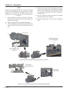
2. Slowly pressurize compressor unit through suction
oil charging port.
3. Check for leaks.
4. Typically, no evacuation is required for open loop
systems. If dry nitrogen was used, it can be bled off
to atmosphere.
5. If evacuation is required, evacuate from suction oil
charging port.
6. Open all valves previously closed and close all
valves previously opened. Remove tags as per the
local lockout/tagout procedure.
7. Turn the motor and oil pump disconnect switches
to the ON position.
8. The compressor unit can now be started, refer to
Start-Up procedure in Section 4.
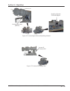
Solenoid
Shut-off
Valve
Needle
Valve
Line to
Suction
Line
from Oil
Separator
Line from Needle
Valve to Suction
Line from Oil Separator
to Shut-off Valve
Figure 5-1. Suction By-Pass Valve Location (Equalizing Solenoid) (2 of 2)