


5 – 9
VSG/VSSG • Installation, Operation and Maintenance Manual •Vilter/Emerson • 35391SSG
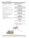
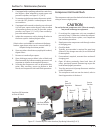
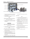
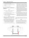
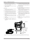
Figure 5-7. Oil Pump Strainer and Drain Valve
Strainer
Drain Valve
Oil Pump
Strainer
Bolts Strainer CoverNuts
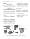
WARNING
Avoid skin contact with any condensate or oil. Wear
rubber gloves and a face shield when working with
condensate or oil. Failure to comply may result in
serious injury or death.
1. Shut down the compressor unit, refer to Stopping/
Restarting procedure in Section 4.
2. Turn disconnect switches to the OFF position for
the compressor unit and oil pump motor starter, if
equipped.
3. Close shut-off valves located before the strainer
and at the oil fi lter(s) inlet.
4. Position drain pan under drain valve.
5. Open strainer drain valve and allow oil to complete-
ly drain, see Figure 5-7.
6. Remove bolts securing strainer cover to strainer.
Remove strainer cover, gasket and element. Retain
gasket.
7. Inspect gasket for damage, replace as required.
8. Wash element in solvent and blow it with clean air.
9. Inspect element for damage, replace as required.
10. Clean strainer cavity with clean lint-free cloth.
11. Install in reverse order of removal. For torque speci-
fi cations, see Appendix A.
12. Close strainer drain valve.
13. Open shut-off valves.
14. Check replaced components for leaks.
15. Turn disconnect switches to the ON position for
the compressor unit and oil pump motor starter, if
equipped.
16. Start compressor unit.
Section 5 • Maintenance/Service
Oil Pump Strainer
NOTICE
Dispose of the oil in a appropriate manner following
all Local, State and Federal ordinances regarding the
disposal of used oil.
To clean the oil pump strainer, proceed with the follow-
ing steps.
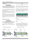
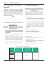
WARNING
At shutdown, open any other valves that may trap
liquids to prevent serious injury and/or damage to
equipment.
WARNING
Follow local lockout/tagout procedure. Failure to
comply may result in serious injury, death and/or
damage to equipment.
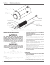
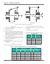
on pipe stub.
13. Remove tubing.
14. Position cover plate and fl at washer on hold-down
rod on end of the coalescing fi lter.
15. Install nut to secure fl at washer and cover plate to
coalescing fi lter. Tighten nut to 25 ft-lbs.
16. Install second nut to prevent fi rst nut from moving.
17. Repeat steps 10 to 16 for installing additional co-
alescing fi lters.
18. Position oil separator manhole cover on oil separa-
tor vessel.
19. Install bolts to secure oil separator manhole cover
to oil separator vessel.
20. Tighten bolts, see Appendix A.
21. Perform Compressor Unit Leak Check procedure.
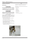
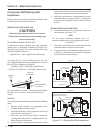
View From Back of Oil Pump Strainer