


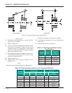
5 – 16
VSG/VSSG • Installation, Operation and Maintenance Manual •Vilter/Emerson • 35391SSG
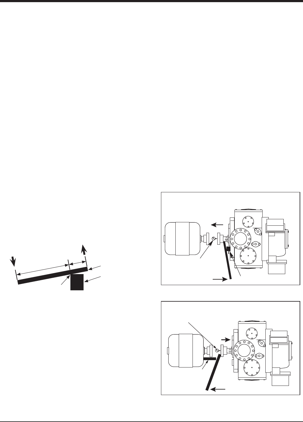
motor and use the lever arm to push the input shaft
towards the compressor. Record measurement
5. Add both measurements. If measurement is out of
allowable tolerance shown in Table 5-7, the bearing
may need to be replaced. Contact Vilter Customer
Service.
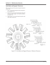
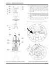
BEARING RADIAL FLOAT INSPECTION
6. Install dial indicator to the compressor frame and
zero indicator, see Figure 5-12.
NOTE
Do not exceed maximum applied force. For
maximum applied forces of all compressor models,
see Table 5-7.
7. Place lever arm and fulcrum underneath hub and
push hub upwards. Record measurement.
8. If measurement is out of allowable tolerance shown
in Table 5-7, the bearing may need to be replaced.
Contact Vilter Customer Service.
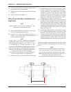
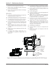
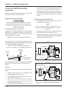
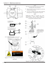
Top View
Small wooden block or fulcrum.
Direction of
shaft movement.
Shaft being pushed by use of lever.
Applied Force
Rigidly attach dial indicator.
Position on axis of compressor.
Top View
Wooden block
or fulcrum
Direction of
shaft movement.
Rigidly attach dial indicator.
Position on axis of compressor.
Applied Force
Shaft being pushed by use of lever.
Figure 5-11. Bearing Axial Float Inspection
Compressor Shaft Bearing Float
Inspections
If fl oat measurements are out of tolerance, contact Vilter
Customer Service for further assistance.
BEARING AXIAL FLOAT INSPECTION
CAUTION
When taking the measurements, do not exceed
300 lbs of force at point of contact or damage may
result to the bearings.
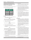
DETERMINE MAXIMUM APPLIED FORCE
To determine maximum applied force, take maximum
applied force at hub/shaft multiplied by length of A
and divide by length B. This is the maximum force that
should be applied on the lever.
(Applied Force x A)/B = Applied Force (Maximum)
So, using a 36” (or 1 m) lever with pivot space of 6” (or
15 cm) would make the maximum applied force to be 60
lbf (or 235 N). Calculation is as follows:
(300 lbf x 6”)/30” = 60 lbf (Max. Applied Force)
(1335 N x 15 cm)/85 cm = 235 N (Max. Applied Force)
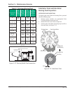
BA
Lever
Wooden Block
or Fulcrum
Applied
Force
Force at
Hub/Shaft
Pivot Point
As a quick reference, Table 5-7 shows maximum applied
forces for 36” lever with 6” pivot for all compressor
models.
MEASURE
To inspect bearing axial fl oat, proceed with the following
steps:
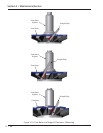
1. Remove center member, see appropriate Drive
Coupling Replacement procedure.
2. Install dial indicator to the compressor frame and
zero indicator, see Figure 5-11.
3. Place lever arm and fulcrum behind compressor
coupling half and push the coupling towards the
motor. Record measurement.
4. Re-zero indicator, now position the fulcrum on the
Section 5 • Maintenance/Service