


5 – 17
VSG/VSSG • Installation, Operation and Maintenance Manual •Vilter/Emerson • 35391SSG
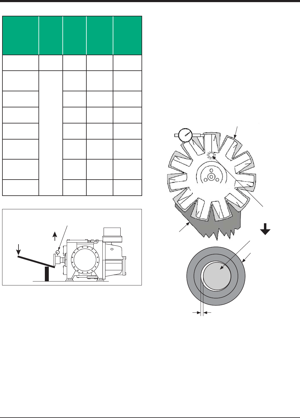
Gate Rotor Float and Gate Rotor
Bearing Float Inspection
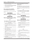
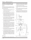
GATE ROTOR FLOAT INSPECTION
To inspect gate rotor fl oat and bearing fl oat, proceed
with the following steps:
1. Remove center member, see appropriate Drive
Coupling Replacement procedure.
2. Remove the side covers from compressor.
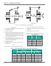
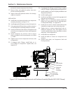
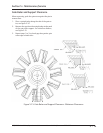
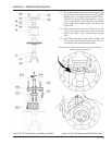
3. Position gate rotor blade and damper pin at 90° to
the main rotor, see Figure 5-13.
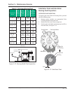
Figure 5-13. Gate Rotor Float
Dial Indicator
Gate Rotor
Support
Gate Rotor Blade
Main Rotor
Float
Damper Pin
and Bushing
Bushing
Damper Pin
Section 5 • Maintenance/Service
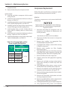
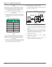
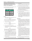
Table 5-7. Maximum Bearing Float
Compressor
Model
Max.
Axial
Float
in. (mm)
Max.
Radial
Float
in. (mm)
Max.
Force
at Hub/
Shaft
lbf (N)
Max.
Applied
Force
(36” Lever, 6”
Pivot)
lbf (N)
All
0.002
(0.051)
-
300
(1335)
60
(267)
151, 181, 201,
152, 182, 202,
301, 361, 401
-
0.006
(0.152)
100
(444)
20
(89)
501, 601, 701
0.007
(0.178)
150
(667)
30
(133)
291, 341, 451,
601
0.007
(0.178)
150
(667)
30
(133)
751, 901
0.006
(0.152)
200
(890)
40
(178)
791, 891,
1051, 1201,
1301
0.006
(0.152)
300
(1335)
60
(267)
1501, 1551,
1801, 1851,
2101
0.007
(0.178)
400
(1780)
80
(356)
2401, 2601,
2801, 3001
0.006
(0.152)
600
(2670)
120
(534)
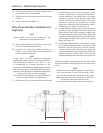
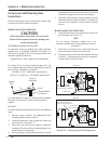
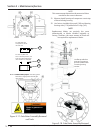
Side View
Rigidly attach dial indicator.
Direction of shaft
movement.
Applied Force
Shaft being pushed by use of lever.
Figure 5-12. Bearing Radial Float Inspection